Aiming at the phenomenon of thermal barrier coating peeling of engine working turbine blades during test run, this study found out the root cause of coating peeling during the use of the product through macroscopic observation, scanning electron microscope morphology analysis and energy spectrum microcomponent analysis, combined with the investigation results of the whole process process, and put forward suggestions for improvement of the processing technology of subsequent parts.
Electron beam physical vapor deposition (EB-PVD) thermal barrier coating has been widely used in aero engine blades, and has become an indispensable key technology for aero engine blades. EB-PVD technology is a technology that uses a high energy density electron beam to heat the material to be vaporized into a water-cooled crucible in a vacuum environment, so that it reaches a molten gasification state, and evaporates to the substrate under the action of a deflecting magnetic field to condense into a coating. There are many kinds of EB-PVD thermal barrier coating structures, including double layer structure, gradient structure and multilayer structure, of which the most widely used is the double layer thermal barrier coating. The double-layer thermal barrier coating is composed of a ceramic top layer and a metal bonding layer. The ceramic layer mainly plays the role of heat insulation, and the metal bonding layer mainly plays the role of alleviating the thermal expansion mismatch between the matrix and the ceramic layer, and improving the resistance of the matrix to high temperature oxidation corrosion. In the actual working environment, the interface between the bond layer and the ceramic layer will form an oxide layer, the main component of which is α-Al2O3, thus inhibiting the further diffusion of O elements into the coating . The main challenge facing the application of thermal barrier coatings is the durability of the coating, especially the coating resistance to spalling, which is influenced by many factors, such as the stress state in the ceramic layer, the microstructure of the bond layer, the thickness and stress state of the TGO layer, and the fracture resistance of the various interfaces between the bond layer and TGO. At present, it is recognized that the oxidation of the bond layer is the key factor to determine the life of the thermal barrier coating.
1. Test process and results
1.1 Macroscopic observation of coating spalling morphology
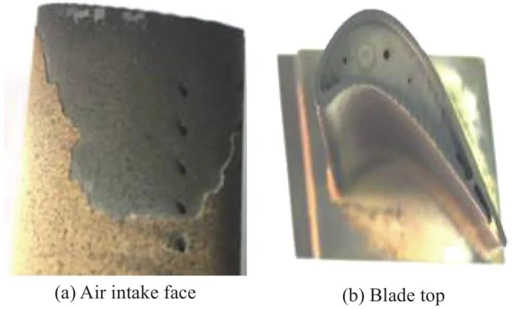
9 h after the engine test, it was found that the coating on the surface of the working blade was spalling, and the spalling area exceeded the standard requirements. Its macro morphology is shown in Figure 1.
1.2 Comparative analysis of coating before and after use
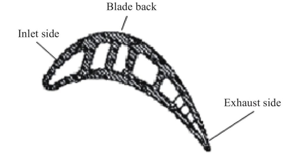
In order to further analyze the causes of leaf coating peeling, the service leaves were compared with the new leaves of the same batch, and the coating components and microstructure of the blade tips and middle parts of each leaf were compared and analyzed according to the leaf positions shown in Figure 2.
1) Comparison of leaf macro morphology. The service blade and the new blade were compared and observed, and the morphology was shown in Figure 3. The coating peeling of service blade is mainly concentrated in the inlet edge and exhaust edge of blade near the blade tip.
2) Chemical composition analysis. Samples were taken from the tip of the blade and the middle of the blade body, and metallographic samples were prepared after hot Mosaic. According to the detection parts shown in Figure 2, the coating components on each part of the blade were analyzed by energy spectrum. The results showed that the content of main element in the bottom layer of the peeled leaves was basically the same as that in the same batch of uninstalled leaves, but there was no obvious difference in the content of main element in the surface layer.
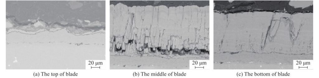
3) Coating morphology analysis. Metallographic samples were observed by scanning electron microscopy, and the results were shown in Figure 4. It can be seen from the figure that the bottom layer of the blade where the coating is peeled off is intact, and some surface layer tissue remains on the bottom layer. The coating is broken from the root of the surface layer columnar crystal, and there is about 1 μm TGO layer between the surface layer and the bottom layer. Further, the complete coating structure at different positions of the blade was analyzed, and the microscopic morphology from the inlet edge to the exhaust edge was observed in the middle section of the blade. At the inlet edge of the middle section of the blade, the cylindrical crystal of the surface layer has cracked along the root, indicating that the coating starts to peel off at the tip of the blade, and the fracture extends to the middle of the blade. On the other hand, the surface layer columnar crystal structures at the back of the leaf and the exhaust edge are clustered together, not in a feathery distribution , the spacing between columnar crystals is not obvious, and the root of the columnar crystal is looser than the tip.
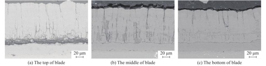
Scanning electron microscopy was performed on different positions of uninstalled blades of the same batch, and the results were shown in Figure 5. As can be seen from Figure 5, the coating structure of the newly made leaves is the same as that of the peeled leaves. The upper end of the columnar crystal is densely distributed, and the surface layer structure is formed by stacking layers. There is an obvious TGO layer between the surface layer and the bottom layer, and the thickness is about 1μm. The existence of TGO layer between the bonding layer and the ceramic layer on the blade indicates that during the deposition of the ceramic layer, there is a certain amount of O in the furnace, which promotes the formation of TGO layer, and the vacuum degree of the furnace may not meet the standard requirements, so that the TGO layer is first formed at the junction of the bottom layer and the surface layer. At the same time, the surface ceramic cracking along the columnar crystal also exists at the tip of the blade.
The process of blade thermal barrier coating is as follows: blade surface pretreatment → multi-arc ion plating deposition base → vacuum diffusion → ultrasonic cleaning → vacuum electron beam deposition surface layer. During its processing, both the metal bonding layer and the ceramic layer are deposited under vacuum, so a TGO layer about 1 μm thick should not be produced between the bonding layer and the ceramic layer. The existing thermal barrier coating preparation process does not contain the TGO layer for tissue detection, so the impact of the TGO layer generated in the preparation process on the performance and service life of the thermal barrier coating needs to be demonstrated in detail, so it is not necessary to go into details here. However, if the vacuum degree in the furnace does not meet the requirements, the structure and properties of the ceramic surface may affect the service life of the thermal barrier coating, which is verified by experiments in this study.
1.3 Microhardness test
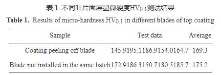
The hardness of the ceramic surface of the two kinds of blades was tested respectively, and the results are shown in Table 1. It can be seen that there is no significant difference in the hardness value of the ceramic surface of the coated peeling blade and that of the uninstalled blade in the same batch, indicating that the hardness value of the blade in the same batch does not change significantly before and after use.
1.4 Verification test
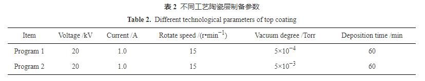
The ceramic layer of the thermal barrier coating is carried out under the electron beam physical deposition process. ZrO2 is heated in a vacuum furnace until it evaporates from the ingot, and then slowly deposited on the surface of the blade. The shape and thickness of the ceramic layer growth are ensured by controlling parameters such as current, vacuum degree and deposition time in the vacuum furnace. After process review, it is found that there are records of replacing gun wire or mechanical pump oil in vacuum furnace, which will directly affect the vacuum degree of vacuum furnace, and then affect the growth of ceramic coating columnar crystals. In order to verify whether the vacuum degree has an effect on the morphology and properties of the cylindrical crystals of the ceramic layer, the deposition tests of different ceramic layers are carried out using the process parameters in Table 2.
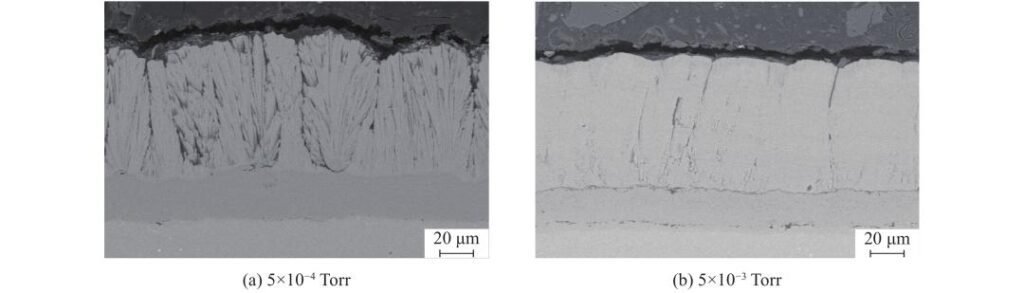
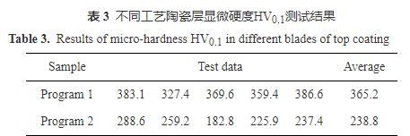
The leaf coating was observed by electron microscope under two conditions. The results show that under the same voltage, current and deposition time, when the vacuum degree in the furnace is 5×10⁻⁴ Torr, the ceramic columnar crystals appear feathery or wheat-like, and there is no TGO layer between the bonding layer and the ceramic layer (FIG. 6a). When the vacuum degree was 5×10⁻³ Torr, the columnar crystals of the ceramic coating were coarse and did not show a feather-like or spike-like shape. The microstructure of the root of the columnar crystals was relatively loose compared with that of the end, and the microstructure was similar to that of the uninstalled leaves, and there was a TGO layer between the bonding layer and the ceramic layer (FIG. 6b). At the same time, the hardness of the ceramic coating under the two vacuum degrees was tested, and the results showed that the hardness of the ceramic layer was higher under the 5×10⁻⁴ Torr vacuum degree, while the hardness of the ceramic layer deposited under the 5×10⁻³ Torr vacuum degree was lower (Table 3).
2. Conclusion
1) The ceramic layer of the faulty blade is broken from the root of the surface layer, and the structure of the root of the columnar crystal is loose, and the middle and upper part of the columnar crystal are clustered and distributed in layers. The hardness value is lower than that of the normal ceramic layer, and the structure is significantly different from that of the normal ceramic coated columnar crystal.
2) Vacuum degree has a direct influence on the growth morphology of ceramic coating. When the vacuum degree meets the standard requirements, the columnar crystals grow like feathers or ears. When the vacuum degree is lower than the standard requirements, the root of the columnar crystal is loose, the middle and upper part of the columnar crystal are dense, and there is an obvious TGO layer between the bonding layer and the ceramic layer.
3) The failure of the ceramic layer of the faulty blade to meet the use requirements is caused by the abnormal condition of the physical deposition equipment, resulting in the deposited ceramic layer organization does not meet the standard requirements.
- WhatsAPP:+86 135 4409 5201
- E-mail:peter@turbineblade.net
- Address:4E137, 4th Floor, Building 210, Tairan Science Park, Tairan 4th Road, Tian ‘an Community, Shatou Street, Futian District, Shenzhen. China