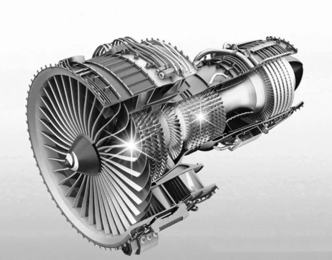
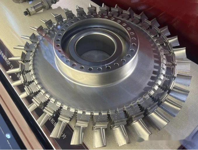
Introduction to turbine blades
The component with the worst working conditions in the turbine engine is also the most important rotating component. In the hot end components of aircraft engines, the turbine blades are subjected to high-temperature gas erosion and temperature changes during the engine start-up and shutdown cycles, and the rotor blades are subjected to centrifugal force at high speeds. The material is required to have sufficient high-temperature tensile strength, endurance strength, creep strength, as well as good fatigue strength, oxidation resistance, gas corrosion resistance and appropriate plasticity. In addition, long-term organizational stability, good impact strength, castability and low density are also required.
The gas inlet temperature of advanced aircraft engines reaches 1380℃ and the thrust reaches 226KN. The turbine blades are subjected to aerodynamic and centrifugal forces, with the blades bearing a tensile stress of about 140MPa; the blade root bears an average stress of 280~560MPa, and the corresponding blade body bears a temperature of 650~980℃, and the blade root is about 760℃.
The performance level of turbine blades (especially the temperature bearing capacity) has become an important indicator of the advanced level of a model of engine. In a sense, the casting process of future engine blades directly determines the performance of the engine and is also a national aviation industry. A significant mark of level.
Blade shape design
Since there are many blades, if they are designed into straight regular shapes, a lot of processing technology can be reduced, the design difficulty can be lowered, and a lot of costs can be reduced. However, most of the blades are twisted and curved.
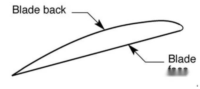
Let me first introduce to you some basic concepts of leaves.
First, what is a runner? Below are two typical runner diagrams.
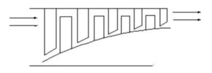
Compressor flow diagram
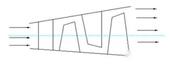
Turbine flow path diagram
Secondly, what is the calculation formula for the circumferential speed? In the flow channel, the circumferential speed is different at different radii (this can be obtained according to the calculation formula in the figure below)
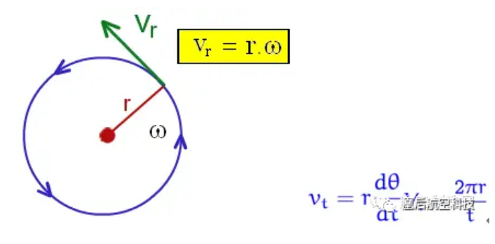
Circumferential speedFinally, what is the angle of attack of the airflow?The angle of attack of the airflow is the angle between the airflow and the blade chord relative to the blade velocity direction.
Taking the airplane wing as an example, the angle of attack of the airflow is shown. Next, why the blade must be twisted is explained? Since the circumferential speeds at different radii in the flow channel are different, the angle of attack of the airflow at different radius primitive levels varies greatly; at the tip of the blade, due to the large radius and the large circumferential speed, a large positive angle of attack is caused, resulting in serious airflow separation on the back of the blade; at the root of the blade, due to the small radius and the small circumferential speed, a large negative angle of attack is caused, resulting in serious airflow separation on the blade basin of the blade.
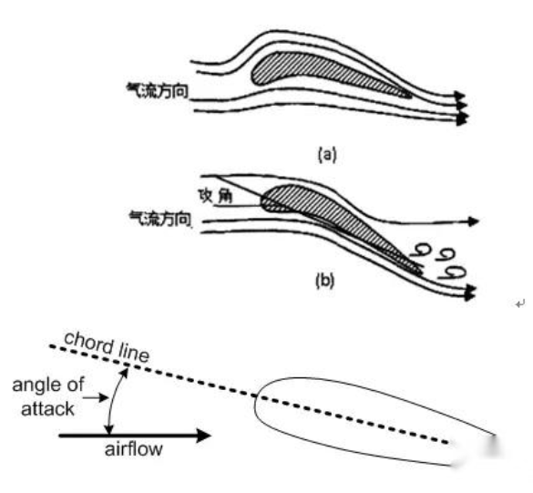
Therefore, for straight blades, except for a part of the nearest mid-diameter that can still work, the rest of the parts will produce serious airflow separation, that is, the efficiency of a compressor or turbine working with straight blades is extremely poor, and may even reach the point where it cannot operate at all. This is why the blades must be twisted.
Development History
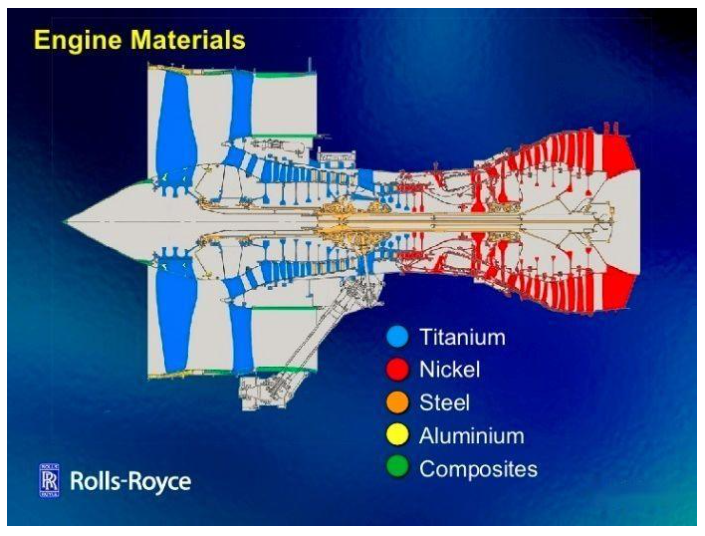
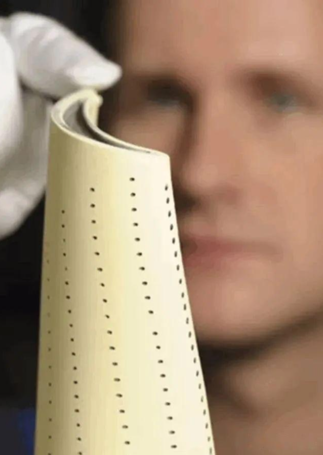
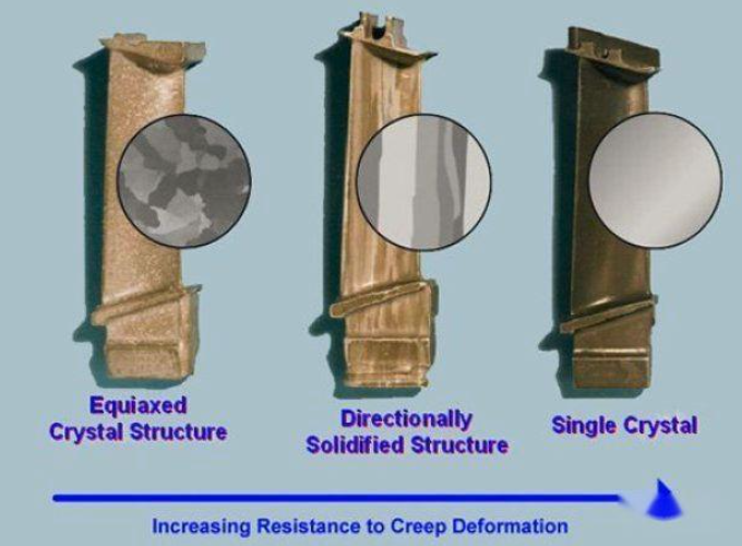
As the power of aircraft engines continues to increase, it is achieved by increasing the compressor inlet temperature, which requires the use of advanced blades with higher and higher temperature resistance. In addition to high temperature conditions, the working environment of hot end blades is also in an extreme state of high pressure, high load, high vibration, and high corrosion, so the blades are required to have extremely high comprehensive performance. This requires the blades to be made of special alloy materials (high temperature alloys) and special manufacturing processes (precision casting plus directional solidification) to make special matrix structures (single crystal structures) to meet the needs to the greatest extent possible.
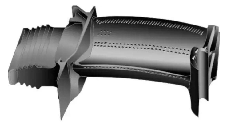
Complex single-crystal hollow turbine blades have become the core technology of current high thrust-to-weight ratio engines. It is the research and use of advanced single-crystal alloy materials and the emergence of double-walled ultra-air-cooled single-crystal blade manufacturing technology that have enabled single-crystal preparation technology to play a key role in today’s most advanced military and commercial aviation engines. At present, single-crystal blades have not only been installed on all advanced aviation engines, but are also increasingly used in heavy-duty gas turbines.
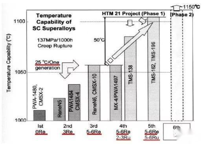
Single crystal superalloys are a type of advanced engine blade materials developed on the basis of equiaxed crystals and directional columnar crystals. Since the early 1980s, the first generation of single crystal superalloys such as PWA1480 and ReneN4 have been widely used in a variety of aircraft engines. In the late 1980s, the second generation of single crystal superalloy blades represented by PWA1484 and ReneN5 were also widely used in advanced aircraft engines such as CFM56, F100, F110, and PW4000. At present, the second generation of single crystal superalloys in the United States have matured and are widely used in military and civilian aircraft engines.

Compared with the first-generation single crystal alloys, the second-generation single crystal alloys represented by PW’s PWA1484, RR’s CMSX-4, and GE’s Rene’N5 have increased their operating temperature by 30°C by adding 3% rhenium and appropriately increasing the content of molybdenum, achieving a good balance between strength and resistance to oxidation and corrosion.
In the third single crystal alloy Rene N6 and CMSX-10, the alloy composition is optimized in one step, the total content of insoluble elements with large atomic radius is increased, especially the addition of more than 5wt% rhenium, which significantly improves the high temperature creep strength, 1150 The endurance life of the alloy is greater than 150 hours, which is much longer than the life of the first-generation single crystal alloy of about 10 hours, and it also has high-strength resistance to thermal fatigue, oxidation and thermal corrosion.
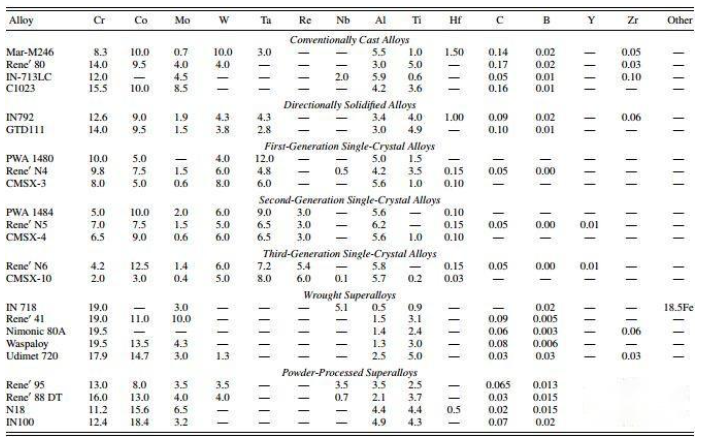
The United States and Japan have successively developed the fourth generation of single crystal alloys. By adding ruthenium, the stability of the alloy microstructure has been further improved, and the creep strength under long-term high temperature exposure has been increased. Its endurance life at 1100 ℃ is 10 times higher than that of the second single crystal alloy, and the operating temperature has reached 1200 ℃. The single crystal composition of the same generation is shown below.
Blade base material and manufacturing technology
Deformed high temperature alloy blades
The development of deformable high-temperature alloys has a history of more than 50 years. The commonly used deformable high-temperature alloys for domestic aircraft engine blades are shown in Table 1. With the increase of aluminum, titanium, tungsten and molybdenum content in high-temperature alloys, the material properties continue to improve, but the hot working performance decreases; after adding the expensive alloying element cobalt, the comprehensive performance of the material can be improved and the stability of the high-temperature structure can be improved.
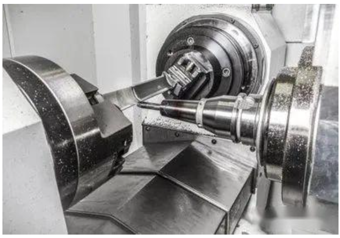
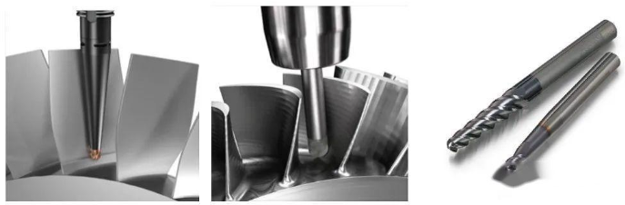
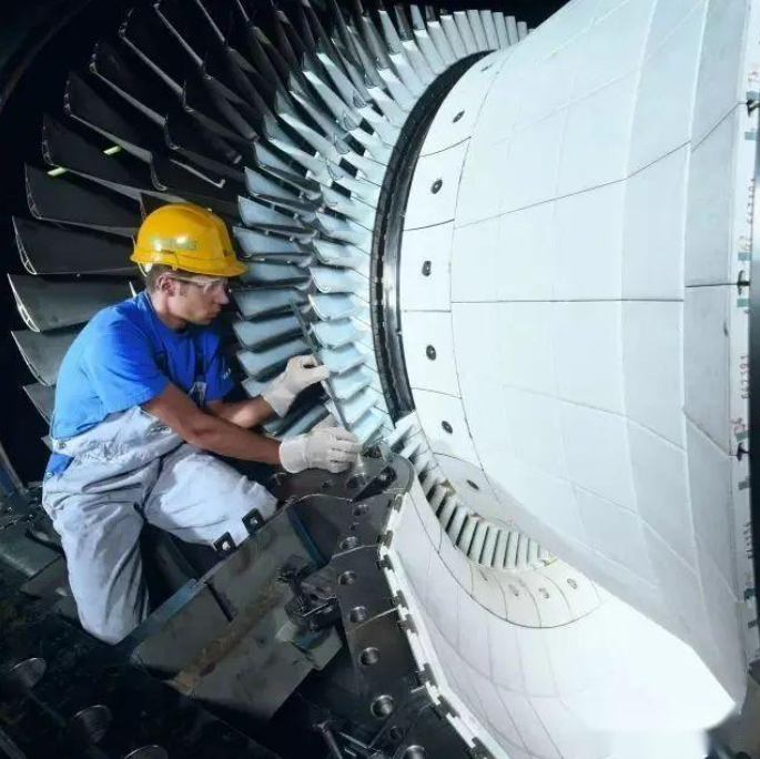
Blades are key parts of aircraft engines, and their manufacturing volume accounts for about 30% of the total engine manufacturing volume.
Aircraft engine blades are thin-walled and easily deformed parts. How to control their deformation and process them efficiently and with high quality is one of the important research topics in the blade manufacturing industry.
With the emergence of high-performance CNC machine tools, the manufacturing process of turbine blades has also undergone major changes. Blades processed using precision CNC machining technology have high precision and short manufacturing cycles, generally 6 to 12 months in China (semi-finishing machining); and 3 to 6 months abroad (no-residue machining).