With the continuous improvement of aircraft engine performance, high thrust-to-weight ratio has become an important indicator of advanced aircraft engine performance. Therefore, the development of advanced high structural efficiency and high-performance materials with lightweight overall structure has become the main development trend. The integral blade ring structure using continuous fiber reinforced titanium-based composite materials has significant advantages in weight reduction and can also withstand circumferential loads. It is the development direction of advanced aircraft engine materials. At present, the integral blade ring is mostly made of continuous single silicon carbide long fiber reinforced titanium-based composite materials, which has the advantages of high strength, high operating temperature and good fatigue and creep properties. Its manufacturing process generally forges ordinary titanium alloy into a blank, then processes it into a blade, and at the same time processes a ring groove on the inside of the blade ring, loads the composite material, and covers the plug-in with ordinary titanium alloy, and then performs hot isostatic pressing, and finally makes it composite into one.

This study mainly conducts vibration fatigue life assessment tests on integral blade rings with two different manufacturing processes: forging heat treatment (FHT) + hot isostatic pressing (HIP) and FHT. Among them, the integral blade ring blade in the FHT+HIP process state is blade I, and the integral blade ring blade in the FHT process state is blade II. The test blade matrix material is TC17 titanium alloy, and the test target for the number of cycles is 3×10⁷. The relevant information of the test piece is shown in Table 1. When blade I cycles to 1.8×10⁷ times, cracks appear near the tip of the blade, and the test is terminated; blade II passes the test assessment. This study analyzes the crack properties and initiation causes of blade I through macroscopic inspection, fracture macro-micro analysis, material analysis, mechanical properties test, and finite element stress simulation to determine the failure cause and failure mode of the blade.
Experimental process and results
Macroscopic inspection
The fluorescence detection results of the crack of blade I are shown in Figure 1. There is a crack fluorescence near the tip of the blade, and the crack has penetrated the thickness of the blade. The crack is about 33 mm away from the air inlet edge of the blade.

Fracture analysis
The crack of the blade was opened, and the macroscopic morphology of the fracture is shown in Figure 2. The fracture is grayish white, which is obviously different from the color of the artificially opened area; the overall undulation of the fracture is small, and obvious radial ridges and fatigue arc features can be seen, indicating that the nature of the crack fracture is fatigue cracking.
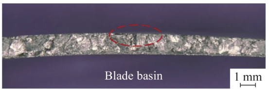
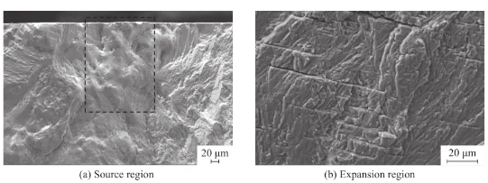
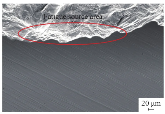
The crack fracture of the blade was observed microscopically using a field emission scanning electron microscope. It can be seen that the radial ridges and fatigue arcs converge on the back surface of the blade, indicating that fatigue starts from here and presents a single source characteristic. The location of the source area is shown in the red line area in Figure 2. Further magnification and observation show that the fatigue source area is heavily worn and no obvious metallurgical defects are observed (black line area in Figure 3a). Energy spectrum analysis of this area shows that the O content in this area is significantly higher than that in the matrix, and no obvious abnormalities are observed in other elements. Clear fatigue bands and secondary cracks can be seen in the extended area, and the fracture nature is further determined to be fatigue (Figure 3b). The blade machining traces can be seen on the side surface of the source area (Figure 4), which has a certain angle with the crack, indicating that it has little effect on promoting crack initiation.
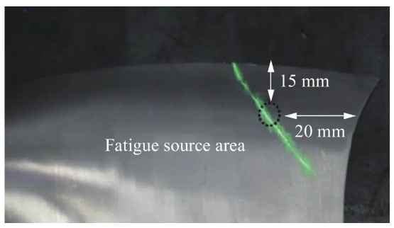
The macroscopic position of the fatigue source area on the back side of the blade is shown in Figure 5. The source area is located about 15 mm from the tip of the blade and about 20 mm from the air inlet edge, and extends to both sides of the blade tip and the air inlet edge.
Material Analysis
The composition analysis of the matrix of the cracked blade I shows that the content of its main alloy elements is basically consistent with the composition of TC17 titanium alloy.
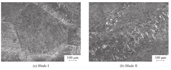
The matrix of blades I and II was sampled, polished, and etched with a corrosive agent of 2% HF+3% HNO3+95% H2O (volume fraction), and then analyzed by metallographic microscope. The metallographic structure is shown in Figure 6. The structure of blade II is a basketweave structure formed after forging and heat treatment in the β zone, with a grain size of about 2~3 levels. The original β grain boundary has been broken and discontinuous during the thermal deformation process, and no obvious abnormality is observed. The structure of blade I is also a basketweave structure, but the grains are coarse, the grain size is lower than 0 0 level, and the size is significantly larger than that of blade II, and there is a straight grain boundary continuous α film.
Stress Analysis
The crack fracture fatigue of blade I originates from the back surface of the blade, which is a certain distance from the blade tip surface and the side edge. In order to analyze the relationship between fatigue origin and stress distribution, the surface stress analysis of the blade is carried out in the ANSYS finite element simulation software.
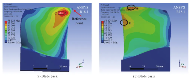
In the blade finite element model, the mesh division unit type adopts C3D10 unit, which is divided into 12 035 units and 48 216 nodes. The first-order bending vibration mode is used for finite element simulation analysis. The reference point is the blade tip of the inlet edge. The boundary condition of the tenon part selects the root fixation. The stress distribution results are shown in Figure 8. It can be seen that there are three high stress level points on the blade. The maximum stress point is on the back side of the blade, and the higher stress point is on the blade tip surface and near the inlet edge of the blade basin side. The corresponding high stress positions are shown in Table 4. The fatigue of blade I originates from the back surface of the blade. The source area is about 15 mm away from the blade tip surface and about 20 mm away from the inlet edge on the back side of the blade, which is basically consistent with the position of the maximum stress C zone of the blade.
Analysis and discussion
The results of fracture macro-micro analysis show that the crack fracture of blade I is flat, with single-source characteristics, fine fatigue bands and secondary cracks, which basically meet the characteristics of high-cycle fatigue. The working cycle number of the blade is 1.87×10⁷, which has exceeded 1/2 of the target cycle number. After the fatigue crack is initiated, the source area is constantly opened and closed to cause oxidation wear, and the crack maintains fatigue steady-state expansion.
The mechanical specimen performance results show that the blade that has only undergone the FHT process can meet the 3×10⁷ assessment requirements at the test bar level fatigue test cycle number. The mechanical specimen fatigue test of the blade that has undergone the FHT+HIP process did not reach the assessment cycle number, and fracture occurred only after 3×10⁶ cycles, with a decrease of one order of magnitude. After the blade in the FHT process state is treated by the HIP process, its strength remains basically stable, but the plasticity and fatigue properties are significantly reduced.
The manufacturing process of blade II is FHT, which can obtain basket structure after treatment. The needle-shaped α phase of basket weave is distributed inside the original β grains. The β phase after aging heat treatment is between the needle-shaped α phases, that is, the secondary α phase precipitated during the aging process is dispersed on the β matrix, which significantly improves the strength of the matrix, especially the fracture performance and creep performance. Therefore, the blade has good fatigue performance. The manufacturing process of blade I is FHT+HIP. After forging, the process is HIP treatment at 920 ℃ and heat preservation for 3 hours, which is equivalent to a high-temperature solution treatment of the blade. The grains grow significantly, and the metastable β structure will precipitate secondary α phase and continuously distribute at the β grain boundary, which makes the crack easy to extend along the grain boundary, which will have an adverse effect on the strength, plasticity and fatigue resistance of the blade.
Finite element analysis shows that the maximum stress point of the blade is located on the back side of the blade, and the higher stress point is located on the blade tip surface and the inlet edge of the blade basin. By comparing the high stress point with the position of the fatigue source area of the blade I crack, it can be found that the source area is located in the maximum stress area of the blade. Fatigue often originates from the weakest part of the material. If other factors of the blade meet the conditions, the most likely location of fatigue is the maximum stress point C. After the HIP treatment of blade I, the grains grow significantly, continuous α grain boundaries appear, and the overall fatigue resistance of the blade is significantly reduced, so premature fatigue cracking occurs at the maximum stress point. Previous studies have shown that titanium alloys can be forged again after aging treatment. The needle-shaped α phase will undergo dynamic spheroidization and static spheroidization in the secondary forging process and subsequent heat treatment process, and finally obtain a transitional spheroidized structure, which is generally finer than the conventional equiaxed structure. Although the fracture toughness and crack propagation resistance of this spheroidized structure are slightly lower than those of the basket structure, for the integral blade ring forging in this study, this fine spheroidized structure produced by secondary forging after hot isostatic pressing may be more suitable. Therefore, the processing sequence of the integral blade ring can be adjusted, and the blank can be processed into blades after hot isostatic pressing, so as to obtain a fine transitional equiaxed structure and avoid the adverse effect of continuous α-phase grain boundaries on performance.
Contact us
Thank you for your interest in our company! As a professional gas turbine parts manufacturing company, we will continue to be committed to technological innovation and service improvement, to provide more high-quality solutions for customers around the world.If you have any questions, suggestions or cooperation intentions, we are more than happy to help you. Please contact us in the following ways:
WhatsAPP:+86 135 4409 5201
E-mail:peter@turbineblade.net