In order to better evaluate the directional solidification process, the dendrite microstructure was described by measuring the primary dendrite spacing (PDAS) in different regions on cross-section 4 and cross-section 9 of some blades [Figure 3(a) and (b)]. To do this, we use the relation PDAS =√(A/N), where A is the region being analyzed and N is the number of dendrite nuclei on a given region. The results show that the values of PDSA in castings are different under different measuring positions and directional solidification methods.
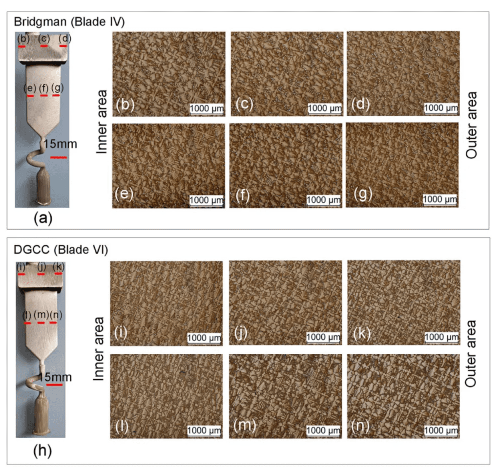
FIG. 2 Sample dendrite microstructure of the outer, middle and inner regions of the platform and airfoil produced by the Bridgeman method (b) to (g) and DGCC gas cooled casting method (i) to (n).
In the first step, the PDSA values of different blades located on the circumference of the mold shell were evaluated experimentally. This is done to determine the uniformity of solidification conditions in different parts of the mold shell. In this study, 5 castings were removed from each mold shell. Figures 3(a) and (b) show the results of PDSA values for different blade midbodies and airfoils. A very small PDAS difference was found in the subsequent lobes of the shell circumference. This difference is reflected in the inner and intermediate areas of these blades, where the difference in PDAS values for blades using the DGCC gas cooled casting process is very small. For example, in the middle region of blade section 4, blade I has the largest PDAS value of 366 μm, while blade IV has the smallest PDAS value of 355μ m. Therefore, for the blades produced by DGCC gas cooling casting, the maximum PDAS difference in the middle area of the airfoil is only 11 microns. For the Bridgman process, the largest difference in PDAS values was 51 μm, also in the middle region of the blade, between blade III and V. However, the variation in the dendrite microstructure (PDAS) values between the subsequent platforms of the blades located at the circumference of the mold shell increases significantly in both Bridgman and DGCC processes. Based on the analysis of PDAS values in the airfoil, it is found that the solidification conditions of DGCC gas cooling casting process are more consistent on the shell circumference than that of Brichman process.
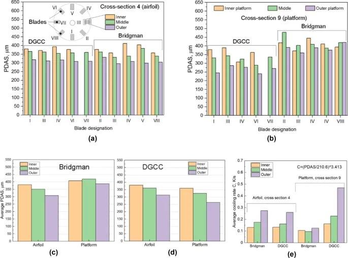

Then, the average primary dendrite arm spacing PDAS for the outer, middle and inner regions of the airfoil and the platform are calculated. This value is based on five blades produced by the previously used Bridgman process and DGCC gas cooled casting method, the results of which are shown in Figure 3(c) and (d). The results show that the average PDAS value of the blade airfoil (cross section 4) produced by DGCC gas cooling casting method is very close to the PDAS value of the primary dendrite arm spacing obtained by the Bridgeman process [Figure 3(c) and (d)]. However, in the platform, the primary dendrite arm spacing PDAS values of DGCC gas cooled casting process are significantly smaller than those obtained by the traditional Bridgman method.
The change of PDAS value was also observed on the blade cross-section width. In general, regardless of the production method used, the PDAS value reaches a minimum in the airfoil area facing the cooling ring and a maximum in the inner area of the casting. In both methods of experimental comparison, the average difference in PDAS between the outer and inner regions of the casting reaches about 50μm. In the platform, the trend of uneven PDAS across the cross-section is also evident. The difference in PDAS values between the outermost regions of the platform increases significantly, especially when the DGCC gas cooled casting process is used, the PDAS value can reach about 100μm, compared to about 20μm when the Bridgman process is used. For the DGCC gas cooled casting process, the increase in the non-uniformity of PDAS values at the upper part of the blade is mainly due to a significant decrease in the mean value of PDAS in the external platform of about 260μm. Compared to the Bridgman method, smaller PDAS values of about 50μm can be found in the internal blade platforms produced by the DGCC gas cooled casting method.

Next, in order to better explain the reasons for the different dendrimic microstructure in the blade platform generated by DGCC gas cooling casting method and the substantial refinement of the microstructure (Figure 4), the dendrimic microstructure along the entire height of the blade was analyzed in detail. Blades IV and VI manufactured by Bridgman method and DGCC gas cooled casting method were selected for study, respectively. The microstructure of 9 cross sections in the inner, middle and outer regions of the blade was analyzed. The results show that the PDAS value of the castings produced by Bridgman method has a tendency to increase in blade height. The smallest PDAS values are found in the airfoil, while the largest values are found in the platform. Compared with Bridgman method, the blades produced by DGCC gas cooling casting method have the opposite trend of PDAS value change. In DGCC gas cooling casting process, the PDAS value reaches the maximum value in the lower part of the blade and the minimum value in the platform.
In general, in blades produced by the Brichmann method with typical solidification conditions, the largest PDAS values can be found in areas where the thickness of the casting is greatest (such as platforms), while the smallest values occur in the blade airfoil. The distribution of PDAS values on blades obtained by DGCC gas cooling casting is not commonly seen on blades produced using the Bridgeman method. It is well known that the PDAS value depends on the axial temperature gradient G and the solidification rate v, and the relationship is as follows: PDAS=K1G-0.5v-0.25, where K1 is the material constant. Based on this relationship, the PDAS value mainly decreases with the increase of temperature gradient and, to a lesser extent, with the increase of solidification rate.
In the process of directional solidification casting, solidification rate and temperature gradient are difficult to measure. According to the cooling curve, the cooling rate C (C=Gv) related to G and v can be obtained. Therefore, the relationship between PDAS and cooling rate is usually expressed by the following relation: PDAS=K2Cn, where K2 and n are material constants. In order to better understand the directional solidification process, in particular that of DGCC gas cooling casting, known numerical cooling rates of PDAS in designated areas of blades produced by both methods were calculated [Figure 3(e)]. Using the data in Reference 17, assume that the material constant of CMSX-4 nickel superalloy is K2=210.6, n=−0.293. After converting the above equation, the average cooling rate is calculated according to the relation C=(PDAS/210.6)3.413. It is found that the cooling rate on blade section 4 when Bridgman method is used is similar to the cooling rate in the blade airfoil produced by DGCC gas cooled casting method. The cooling rate is greatest near the cooling ring and heater and decreases in the direction of the central axis, which is the shadow effect commonly seen in the Bridgman process, and the main reason for the uneven distribution of PDAS values across the blade width. In general, the distribution of cooling rates obtained across the cross-section of the blade airfoil and the resulting PDAS values are similar, despite the use of two different manufacturing methods. This shows that the thermal effects of the cooling ring and final cooling plate on the middle part of the blade airfoil (cross section 4) are similar to the effects of radiation cooling on the middle part of the blade in the Bridgman process. In the middle area of the blades analyzed, the use of cooling gases did not significantly increase the cooling rate and refine the microstructure.

However, relative to the blade body, the cooling rate on the airfoil is significantly increased. Using the Bridgman method results in a decrease in the cooling rate and an increase in the PDAS value of the airfoil. Although the same shell and heating chamber design and the same crystal pulling rate are used in Bridgman and DGCC gas cooling casting processes, the degree of refinement of the dendriform microstructure observed on the airfoil is completely different in both processes. The results show that the cooling gas injected into the furnace cavity obviously affects the cooling of the mold shell and the directional solidification of the airfoil, but the cooling gas has little effect on the solidification of the blade under the same process parameters.
According to the research of Liu et al. , when the radiation cooling method is used in the Bridgman method, the increase of the casting cross section will lead to the decrease of the temperature gradient at the solidification front, thus increasing the PDAS value. However, in the DGCC gas-cooled casting method, the PDAS value decreases as the cross section increases.
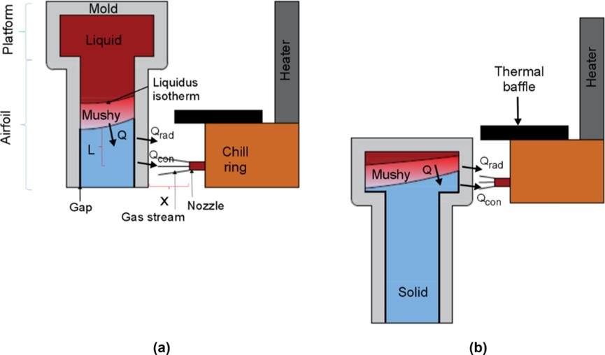
Therefore, it can be inferred that when gas cooling is performed on the die surface, the shape and position of the blade in the assembly component and the position of the relative air flow play a decisive role in the gas cooling effect. Konter et al. pointed out that increasing the horizontal distance X between the nozzle and the surface of the mold shell significantly reduces the convective heat transfer coefficient, thereby reducing the temperature gradient and cooling rate (Figure 5). In the experiment, the width of the blade body is less than the width of the airfoil. Therefore, in the blade part, the horizontal distance between the nozzle and the mold shell is the largest, while in the airfoil part, the horizontal distance between the nozzle and the mold shell is the smallest. In addition, the thickness of the airfoil and the transverse surface of the mold shell are also larger than the thickness of the blade area. In the case of DGCC gas cooling casting, the aerofoil area is more suitable for heat dissipation from the outer surface of the mold shell by high-speed airflow than the blade surface.

The main factors that have a decisive effect on the melt cooling rate and temperature gradient are the location of the injection center line and the position of the cast paste region related to it. Depending on the shape of the casting, the vertical distance L between the solidification front and the paste zone and the nozzle (DGCC gas cooled casting method) or the cooling tank (LMC method) is also different. Miller and Pollock report that the LMC method achieves the maximum axial temperature gradient when almost the entire paste region is immersed in the cooling tank. Under these conditions, heat dissipation along the height of the paste zone is achieved by convective cooling, while the mold shell region located above the solidification front is cooled by less effective radiative cooling. In the Bridgman method, the cooling rate is greatest at the interface between the cooling plate and the cast base. As the distance between the dynamic paste zone and the cooling plate increases, the cooling rate decreases. When this distance is greater than about 25mm, the conducted heat flow in the direction of the cooling plate is very small, and the radiative cooling mode of the cast at this time leads to the heat flow mainly in the lateral direction . Based on the large number of results obtained by the LMC method and Bridgman method, a similar assumption can also be made for the DGCC gas cooling casting method, that is, the vertical distance between the cooling flow and the position of the paste zone should be as small as possible.

According to the results obtained, the directional solidification mechanism of single crystal blades produced by DGCC gas cooling casting method can be proposed. FIG. 5 shows a schematic of the blade at different solidification stages and the position of the paste zone with respect to the gas nozzle. The analysis of the microstructure and cooling rate of the dendritic arms shows that the air flow has little effect on the cooling effect of the blade body. During the solidification of the blade body, the paste region is located above the nozzle position [Figure 5(a)]. The nozzle center line mainly cools the shell area below the temperature of the solid phase line. In this case, the distance from the bottom of the paste zone to the area of the cast (the nozzle position) where the gas jet impacts determines that the conduction path of the heat flow Q is mainly in the axial direction of the casting. At the height of the nozzle position, the heat flow mainly flows along the casting radial through the mold shell, and the heat flow decreases with the increase of the distance from the bottom of the paste area to the nozzle position. Therefore, if the vertical distance between the paste mold area and the nozzle is too large, the thermal effect of the gas injection on the formation of the microstructure will be limited. A large increase in the cross-section of the airfoil relative to the blade body interferes with the axial heat flow [Figure 5(b)]. In order to maintain directional solidification, the solidification rate is reduced, and the liquid phase isotherm also becomes curved due to the transverse heat flow within the airfoil. As a result, the paste zone in the casting moves down to the cooling zone of the furnace. At this solidification stage, the most favorable cooling conditions for microstructure refinement are obtained. The paste zone in the casting is horizontal at the nozzle position. In this case, the cooling gas carries away the heat in the mold shell, and the inner surface of the mold shell is in direct contact with the paste zone. At the junction between the paste area and the inner surface of the mold shell, the thermal resistance of the forming gap is obviously smaller than that of the completely solidified casting area. At the same time, due to the reduction in the length of the axial heat flow path, the thermal resistance of the casting region located below the paste region is also reduced. The horizontal distance between the nozzle and the shell surface is also reduced. As a result, the heat carried away by this gas from the surface of the mold shell increases, so that the temperature gradient on the airfoil increases and the PDAS value decreases.
Sikovok proposed a method to improve the dendrite texture in the full range of leaves. The experimental results show that the position of the gelatinization zone relative to the nozzle may be crucial to improve the effectiveness of casting and the effect of casting cooling. In the DGCC gas cooling casting process, the position of the paste zone in the casting can be controlled by changing the Angle of the nozzle, the crystal pulling speed of the mold shell, the temperature of the heater or the volume flow of the cooling gas flowing out of the nozzle.
In order to reduce the path of heat through the casting, the tilt Angle of the nozzle can be increased so that the air flow is directed towards the mushy area. The increase in heater temperature will cause the paste zone to move downward to the cooling zone and nozzle direction of the casting . A similar result can be achieved by increasing the withdrawal speed of the mold shell . Increasing the volume flow of the gas should improve the removal of heat from the shell surface while moving the solidification front upward towards the heater . However, if the gas flow rate is too high and the nozzle is pointed at the solidification front at the same time, combined with the push of the upward convection flow of the gas inside the heater, it may cause excessive cooling of the mold shell part located in the heated area. Therefore, this will result in a lower temperature gradient at the solidification front. In order to reduce the upward flow of gas while maintaining high efficiency in extracting heat from the mold shell, it may be necessary to improve the thermal isolation between the cooling chamber and the furnace heating chamber. The matching between the heat shield opening and the mold shell may also affect the PDAS value of the blade airfoil region produced by DGCC gas cooling casting method, as shown in Figure 5. In this experiment, the gap between the heat shield and the mold shell during the solidification of the airfoil is larger than the gap during the solidification of the platform (Figure 5). Therefore, the gas cooling effect of the airfoil area may also be lower than that of the platform. The use of a horizontal heat shield, whose open profile better matches the shape of the cross section of the die shell, should significantly reduce the upward flow of gas between the blades and better control the curvature of the solidification front. In addition, the improvement of this process will result in the stabilization of the solidification front (vertical distance L) relative to the position of the heat shield and the nozzle along the blade height direction, which can be critical in DGCC processes. The proposed improvement of DGCC process can improve the refinement of dendrite microstructure in the blade airfoil region .

Blade castings produced by DGCC gas cooling casting process need to control a large number of process parameters during directional solidification. This makes the technique more complex than the Bridgman method. In the DGCC gas cooling casting method, in addition to the typical process parameters such as crystal pulling speed and heating temperature, the volume, flow rate and injection Angle of the gas injected by the nozzle into the furnace cavity must be precisely controlled. This is necessary to achieve the desired shell cooling by convection. Another challenge may be the choice of the number of nozzles, and their placement in the cooling ring at the appropriate distance from the solidification front and the mold shell. In addition, when producing new blade shapes, previously determined optimal process parameters may need to be adjusted, but the same is true of the Bridgman process. During directional solidification, the DGCC gas cooling casting method requires the control of a large number of parameters, which undoubtedly poses problems in the initial selection of conditions for manufacturing single crystal blades, especially considering the limited information on this process in the literature. However, compared with Bridgman method, proper selection of directional solidification parameters can improve the quality of single crystal blade and increase the crystal pulling speed of die. The directionally solidification process of single crystal blades using DGCC gas cooling casting method on industrial scale has certain complexity, and further experiments and numerical simulations of air flow and heat flow in the furnace chamber and mold shell are required, the results of which will be published in the following papers.
In summary, the effect of injecting supersonic gas into the furnace cavity on the cooling effect and microstructure refinement of the mold shell was studied in the production of nickel-based superalloy single crystal blades by DGCC gas cooling casting under industrial conditions. Compared with the Bridgman method, the use of gas jet to cool the die surface results in a change in the directional solidification conditions of the blade castings. The variation trend of PDAS in the whole height of the blades produced by DGCC gas cooling casting is different from that of Bridgman casting. In DGCC gas cooling casting method, PDAS get the maximum value at the lower part of the blade and the minimum value at the platform. In addition, PDAS values of approximately less than 100 μm were observed on the platform for the blades produced by the DGCC gas cooled casting method, and the PDAS values in the airfoil were similar to those produced by the Bridgman method. According to the proposed principle of directional solidification controlled by gas, the change of PDAS value along the blade height mainly depends on the position of gelatinization region horizontal relative to the nozzle position. When the gelatinization zone and the nozzle are at the same level, the gas removes heat from the surface of the mold zone in direct contact with the gelatinization zone, increasing the cooling rate and temperature gradient of the casting, thereby reducing the PDAS value.
Thank you for your interest in our company! As a professional gas turbine parts manufacturing company, we will continue to be committed to technological innovation and service improvement, to provide more high-quality solutions for customers around the world.If you have any questions, suggestions or cooperation intentions, we are more than happy to help you. Please contact us in the following ways:
- WhatsAPP:+86 135 4409 5201
- E-mail:peter@turbineblade.net
