Turbine blades are an important part of aircraft engines, with high temperature, heavy load, and complex structure. The quality of inspection and maintenance is closely related to the durability and service life of the work. This paper studies the inspection and maintenance of aircraft engine blades, analyzes the failure mode of aircraft engine blades, and summarizes the failure detection technology and maintenance technology of aircraft engine blades.

In the design of turbine blades, new materials with higher quality are often used, and the working margin is reduced by improving the structure and processing technology, so as to improve the engine thrust-to-weight ratio. The turbine blade is an aerodynamic airfoil that can achieve equivalent work over the entire length of the blade, thereby ensuring that the airflow has a rotation angle between the blade root and the blade tip, and the rotation angle at the blade tip is greater than that at the blade root. It is very important to install the turbine rotor blade on the turbine disk. The “fir-tree-shaped” tenon is the rotor of the modern gas turbine. It has been precisely processed and designed to ensure that all flanges can bear the load evenly. When the turbine is stationary, the blade has a tangential movement at the tooth groove, and when the turbine rotates, the blade root is tightened to the disk due to the centrifugal effect. The impeller material is an important factor in ensuring the performance and reliability of the turbine. In the early days, deformed high-temperature alloys were used and manufactured by forging. With the continuous advancement of engine design and precision casting technology, turbine blades have changed from deformed alloys to hollow, polycrystalline to single crystal, and the heat resistance of the blades has been greatly improved. Nickel-based single crystal superalloys are widely used in the production of hot end parts of aviation engines due to their excellent high-temperature creep properties. Therefore, in-depth research on the inspection and maintenance of turbine blades is of great significance for improving the safety of engine operation and accurately evaluating the damage morphology and degree of damage of the blades.
Failure modes of aircraft engine blades
Blade low cycle fatigue fracture failure
In actual work, low-cycle fatigue fracture of rotor blades is usually not easy to occur, but under the following three conditions, low-cycle fatigue fracture will occur. Figure 1 is a schematic diagram of blade fracture.
- (1) Although the working stress on the dangerous section is smaller than the yield strength of the material, there are large local defects at the dangerous section. In this area, due to the existence of defects, the larger area nearby exceeds the yield strength of the material, resulting in a large amount of plastic deformation, which leads to low-cycle fatigue fracture of the blade.
- (2) Due to poor design considerations, the working stress of the blade on the dangerous section is close to or exceeds the yield strength of the material. When there are extra defects in the dangerous part, the blade will undergo low-cycle fatigue fracture.
- (3) When the blade has abnormal conditions such as flutter, resonance, and overheating, the total stress value of its dangerous section is greater than its yield strength, resulting in low-cycle fatigue fracture of the blade. Low-cycle fatigue fracture is mainly caused by design reasons, and most of it occurs around the blade root. There is no obvious fatigue arc at the typical low-cycle fracture.
Blade torsional resonance fatigue fracture failure
High-cycle fatigue fracture refers to the fracture that occurs under the torsional resonance of the blade, and has the following representative characteristics:
- (1) Corner drop occurs at the torsional resonance node.
- (2) An obvious fatigue curve can be seen at the fatigue fracture of the blade, but the fatigue curve is very thin.
- (3) The fracture usually starts from the back of the blade and extends to the blade basin, and the fatigue zone occupies the main area of the fracture surface.
There are two main reasons for the torsional fatigue cracks of the blade: one is the torsional resonance, and the other is the extensive rust on the blade surface or the impact of external force.
Blade high temperature fatigue and thermal damage fatigue fracture failure
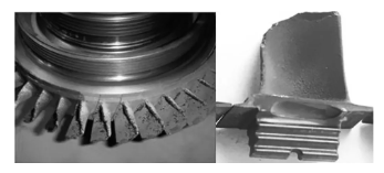
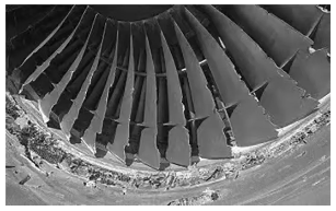
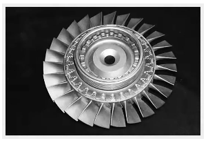
Turbine rotor blades work in a high temperature environment and are subjected to temperature changes and alternating stresses, which lead to creep and fatigue damage of the blades (see Figure 2). For high temperature fatigue fracture of the blades, the following three conditions must be met:
- (1) The fatigue fracture of the blade mainly shows the characteristics of intergranular fracture.
- (2) The temperature at the fracture site of the blade is higher than the limit creep temperature of the material;
- (3) The fatigue fracture site of the blade can only withstand the centrifugal tensile stress of the square waveform, which exceeds the creep limit or fatigue limit at this temperature.
- Generally, fatigue fracture of rotor blades at high temperatures is extremely rare, but in actual use, fatigue fracture caused by thermal damage to the rotor is relatively common. During engine operation, the overheating or overburning of components due to short-term overtemperature under abnormal working conditions is called overheating damage. At high temperatures, fatigue cracks are prone to occur in blades. Fatigue fracture caused by high temperature damage has the following main characteristics:
- (1) The fracture position is generally located in the highest temperature area of the blade, perpendicular to the blade axis.
- (2) The fracture originates from the inlet edge of the source area, and its cross section is dark and has a high degree of oxidation. The cross section of the extension section is relatively flat and the color is not as dark as the source area.
Failure repair technology of aircraft engine blades
On-board borescope inspection
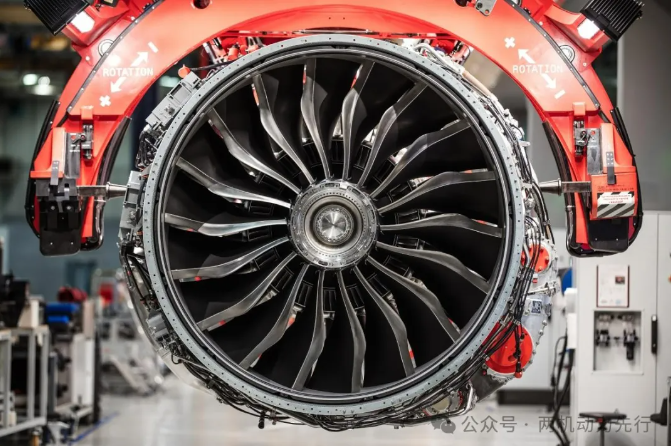
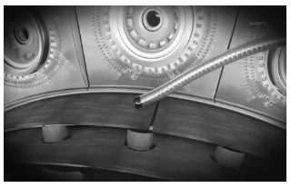
On-board borescope inspection is to visually inspect the turbine blades through a probe in the engine turbine box. This technology does not require disassembly of the engine and can be completed directly on the aircraft, which is convenient and fast. Borescope inspection can better detect the burning, corrosion and debonding of turbine blades, which can help understand and master the technology and health of the turbine, so as to conduct a comprehensive inspection of the turbine blades and ensure the normal operation of the engine. Figure 3 shows the borescope inspection.
Pre-cleaning treatment before inspection in repair workshop
The surface of the turbine blades is covered with deposits after combustion, coatings, and thermal corrosion layers formed by high-temperature oxidation corrosion. Carbon deposition will increase the wall thickness of the blades, causing changes in the original airflow path, thereby reducing turbine efficiency; thermal corrosion will reduce the mechanical properties of the blades; and due to the presence of carbon deposits, the damage to the blade surface is obscured, making detection difficult. Therefore, before monitoring and repairing the blades, the carbon deposits must be cleaned.
Blade integrity testing
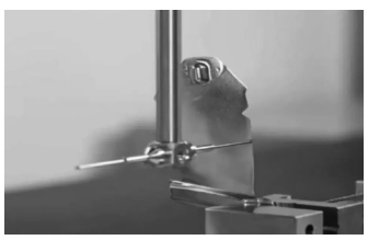
In the past, “hard” measuring instruments such as angle gauges and calipers were used to detect the blade diameter of aircraft engines. This method is simple, but it is easily affected by human interference and has defects such as low accuracy and slow detection speed. Subsequently, based on the coordinate measuring machine, an application for microcomputer automatic control was written, and a measurement system for the geometric dimensions of the blade was developed. By automatically detecting the blade and comparing it with the standard blade shape, the error test results are automatically given to determine the availability of the blade and the required maintenance method. Although the coordinate measuring instruments of different manufacturers have differences in specific technologies, they have the following commonalities: high automation level, fast detection, generally one blade can be detected in 1 minute, and have good expansion capabilities. By modifying a standard blade shape database, various types of blades can be detected. Figure 4 shows the integrity test.
Aircraft engine blade maintenance
Thermal spray technology
Thermal spraying technology is to burn fibers or powdered materials to a molten state, further atomize them, and then deposit them on the parts or substrates to be sprayed.
(1) Wear-resistant coatings
Wear-resistant coatings such as cobalt-based, nickel-based, and tungsten carbide-based coatings are widely used in aircraft engine parts to reduce friction caused by vibration, sliding, collision, friction, and other friction during the operation of aircraft engines, thereby improving performance and service life.
(2) Heat-resistant coatings
In order to increase thrust, modern aircraft engines need to increase the temperature before the turbine to the maximum. In this way, the operating temperature of the turbine blades will increase accordingly. Although heat-resistant materials are used, it is still difficult to meet the requirements of use. Test results show that applying heat-resistant coatings on the surface of turbine blades can improve the heat resistance of parts and avoid deformation and cracking of parts.
(3) Abradable coatings
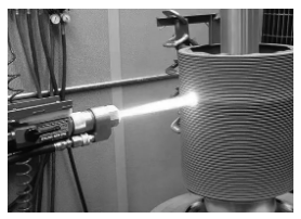
In modern aircraft engines, the turbine is composed of a casing composed of multiple horizontal stator blades and a rotor blade fixed on a disc. In order to improve the efficiency of the engine, the distance between the two components of the stator and the rotor should be reduced as much as possible. This gap includes the “tip gap” between the rotor tip and the fixed outer ring, and the “stage gap” between each stage of the rotor and the casing. In order to reduce the air leakage caused by the excessive gap, the gaps are theoretically required to be zero as much as possible, because the actual error and installation error of the production parts are difficult to achieve; in addition, under high temperature and high speed, the wheel will also move longitudinally, causing the blades to “grow” radially. Due to the bending deformation, thermal expansion and contraction of the workpiece, spraying wear coatings are used to make it have the smallest conscious gap, that is, spraying various coatings on the surface near the top of the blade; when the rotating parts rub against it, the coating will produce sacrificial wear, thereby reducing the gap to a minimum. Figure 5 shows the thermal spraying technology.
Shot Peening
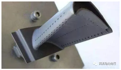
Shot peening technology uses high-speed projectiles to impact the surface of the workpiece, generating residual compressive stress on the surface of the workpiece and forming a strengthening material to a certain extent to improve the fatigue strength of the product and reduce the stress corrosion performance of the material. Figure 6 shows the blade after shot peening.
(1) Dry shot peening
Dry shot peening technology uses centrifugal force to form a surface strengthening layer with a certain thickness on the surface of the workpiece. Although dry shot peening technology has simple equipment and high efficiency, it still has problems such as dust pollution, high noise, and high shot consumption during mass production.
(2) Water shot peening
Water shot peening has the same strengthening mechanism as dry shot peening. The difference is that it uses fast-moving liquid particles instead of shot, thereby reducing the impact of dust on the environment during dry shot peening, thereby improving the working environment.
(3) Rotary plate strengthening
The American 3M Company has developed a new type of shot peening strengthening process. Its strengthening method is to use a rotary plate with shot to continuously strike the metal surface at high speed to form a surface strengthening layer. Compared with shot peening, it has the advantages of simple equipment, easy use, high efficiency, economy and durability. Rotary plate strengthening means that when a high-speed shot hits the blade, the surface of the blade will expand rapidly, causing it to undergo plastic deformation at a certain depth. The thickness of the deformation layer is related to the impact strength of the projectile and the mechanical properties of the workpiece material, and can generally reach 0.12 to 0.75 mm. By adjusting the shot peening process, the appropriate thickness of the deformation layer can be obtained. Under the action of shot peening, when plastic deformation occurs on the blade surface, the adjacent subsurface will also deform. However, compared with the surface, the deformation of the subsurface is smaller. Without reaching the yield point, it is still in the elastic deformation stage, so the non-uniform plasticization between the surface and the lower layer is uneven, which can cause residual stress changes in the material after spraying. The test results show that there is residual compressive stress on the surface after shot peening, and at a certain depth, tensile stress appears at the subsurface. The residual compressive stress on the surface is several times that of the subsurface. This residual stress distribution is very beneficial to improve fatigue strength and corrosion resistance. Therefore, shot peening technology plays a very important role in extending the service life of products and improving product quality.
Coating repair
In aircraft engines, many advanced turbine blades use coating technology to improve their anti-oxidation, anti-corrosion, and wear-resistant properties; however, since the blades will be damaged to varying degrees during use, they must be repaired during blade maintenance, usually by stripping off the original coating and then applying a new layer of coating.
Contact us
Thank you for your interest in our company! As a professional gas turbine parts manufacturing company, we will continue to be committed to technological innovation and service improvement, to provide more high-quality solutions for customers around the world.If you have any questions, suggestions or cooperation intentions, we are more than happy to help you. Please contact us in the following ways:
WhatsAPP:+86 135 4409 5201
E-mail:peter@turbineblade.net