With the improvement of aero-engine performance, lightweight and high-efficiency materials for turbine blades have become a developing trend. Silicon carbide long fiber reinforced titanium matrix composites have attracted much attention because of their good weight reduction effect and ability to withstand annular loads. This turbine blade material has high strength, high temperature resistance and excellent fatigue and creep properties. The manufacturing process involves forging the titanium alloy into a blade shape, reserving slots in the blade ring to fill the composite material, which is then tightly bonded by hot isostatic pressing technology.
In this study, the vibration fatigue life of blades I using FHT+HIP process and blades II using only FHT process were tested, and the target number of cycles was 3×10^7. Blade I terminated the test at 1.8×10^7 times due to a tip crack, while blade II passed the test. By means of macroscopic inspection, fracture analysis, material testing, mechanical testing and finite element simulation, the crack characteristics and causes of blade I were analyzed to determine its failure mode.
1. Test process and results
1.1 Macroscopic Inspection
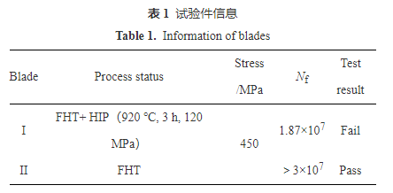
The fluorescence detection results of blade I crack are shown in Figure 1. There were cracks near the tip end of the blade, and the fluorescence showed that the cracks had penetrated the thickness direction of the blade, and the cracks were about 33 mm away from the inlet edge of the blade.
1.2 Fracture analysis
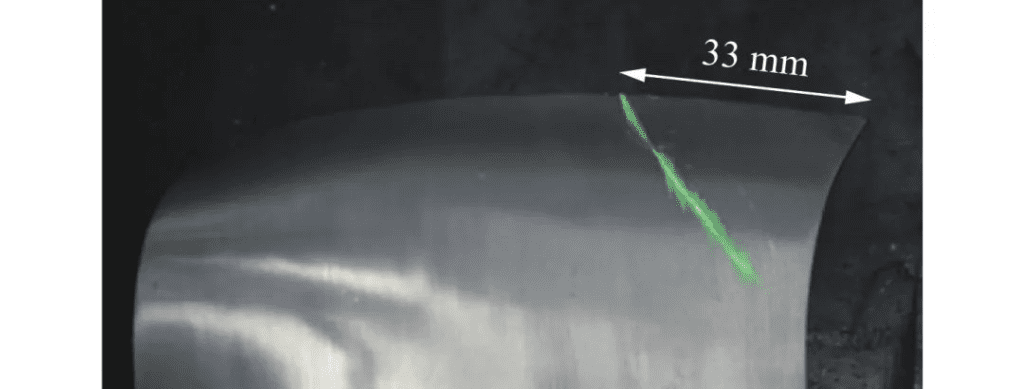
The crack of the blade is opened, and the macro morphology of the fracture is shown in Figure 2. The fracture is grayish white, and the color is obviously different from the artificially opened area. The overall fluctuation of the fracture is small, and the characteristics of radiating edges and fatigue arcs are obvious, indicating that the fracture is fatigue cracking. Focus on the public number: two machine power first, free access to massive two machine data, focus on two machine knowledge and key technologies!
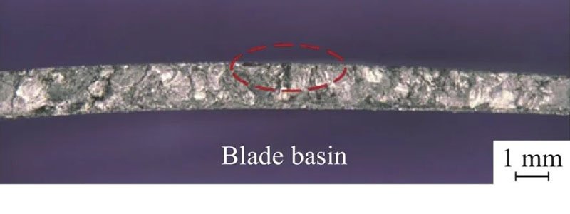
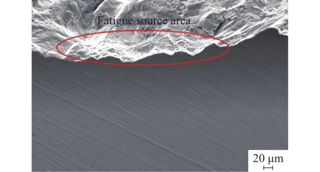
Field emission scanning electron microscopy (SEM) was used to microscopic observe the crack fracture of the blade, and it was found that the radiating edges and fatigue arcs converged on the dorsal surface of the blade, indicating that the fatigue started from there and presented a single-source feature. The location of the source region was shown in the red line area in Figure 2. Further amplified observation showed that the wear in the fatigue source area was heavy and no obvious metallurgical defects were observed (black line area in Figure 3a). The results of energy spectrum analysis show that the O content in this region is obviously higher than that in the matrix, and other elements have no obvious abnormality. Clear fatigue bands and secondary cracks can be seen in the extension area, further confirming the fracture nature as fatigue (FIG. 3b). Blade machining marks (FIG. 4) were visible on the side surface of the source region, which had a certain Angle with the crack, indicating that the promotion of crack initiation was not significant. The macro position of the fatigue source region on the back side of the blade is shown in Figure 5. The source region is about 15 mm from the end face of the blade tip and 20 mm from the inlet edge, and extends to both sides of the blade tip and the inlet edge.

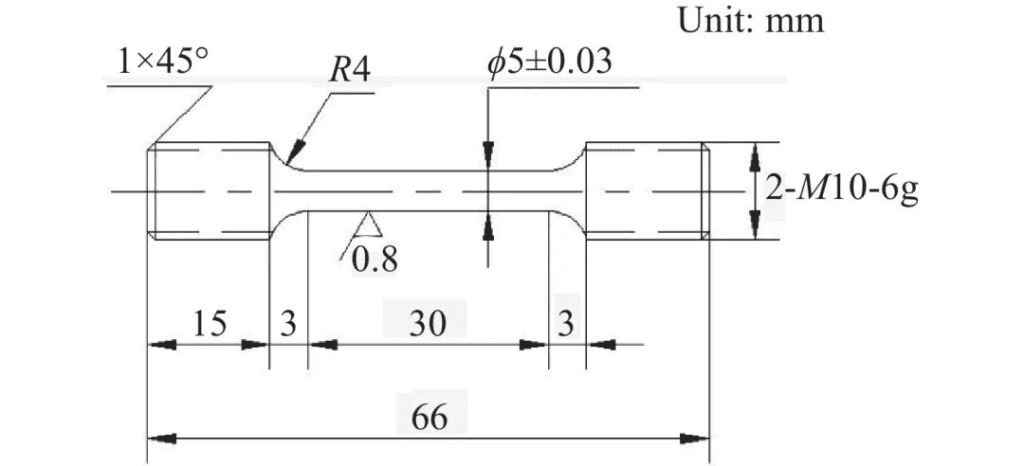
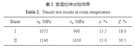
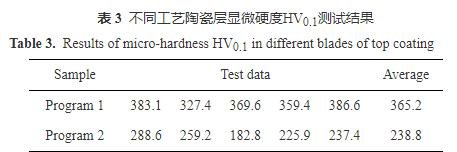
Mechanical performance tests were performed on blades I and II, with 4 samples taken from each blade. Tensile test at room temperature was conducted according to HB 5143-1996 standard, loading speed was 1mm /min, and two samples were tested in each state. The results were shown in Table 2. The high-cycle fatigue test at room temperature was carried out according to HB 5287-1996 standard, and two samples were tested for each state. The results are shown in Table 3.
The yield strength and tensile strength of blade I are slightly lower than that of blade II, the elongation is similar but the section shrinkage is obviously different, and blade I has no obvious necking. Fatigue test at room temperature showed that the fatigue performance of blade I was significantly lower than that of blade II. The blades treated with FHT can meet the test requirements of 3×10^7 times, while the blades treated with FHT+HIP cannot meet the test requirements, which is consistent with the test results of vibration fatigue life.
1.5 Stress analysis
The crack fracture fatigue of blade I originates from the back surface of blade and has a certain distance from the tip end face and side of blade. In order to analyze the relationship between fatigue origin and stress distribution, the surface stress analysis of blade is carried out in ANSYS finite element simulation software.
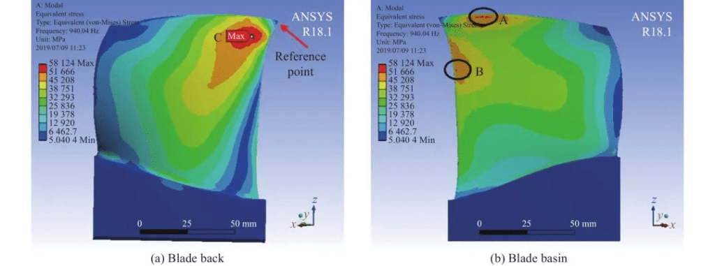
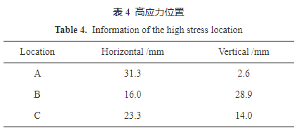
In the finite element model of blade, C3D10 element was used for mesh division, with a total of 12 035 elements and 48 216 nodes. The first-order bending vibration mode was used for finite element simulation analysis. The reference point was the inlet edge blade tip, and the boundary condition of the tenon part was selected as the root support. The stress distribution results were shown in FIG. 8. It can be seen that there are three high stress level points on the blade, the maximum stress point is on the back side of the blade, and the higher stress point is near the tip end face and the inlet edge of the blade basin side. The corresponding high stress locations are shown in Table 4. The fatigue of blade I originates from the back surface of blade, and the source area is about 15 mm from the tip end of blade and 20 mm from the inlet edge, which is basically consistent with the position of the maximum stress zone C of blade.
2. Analysis and discussion
The fracture analysis shows that the crack characteristics of blade I conform to the high cycle fatigue characteristics, and the number of working cycles reaches 1.87×10^7 times. The blades treated by FHT (heat treatment) process can meet the test requirements of 3×10^7 times; However, the blades treated with FHT+HIP (hot isostatic pressing) fractured after only 3×10^6 cycles, and their plasticity and fatigue properties decreased significantly.
Leaf II is treated by FHT process to form a net basket structure, and the acicular α phase is distributed in the β grain, which improves the strength and fatigue properties of the material. On the other hand, after FHT+HIP treatment, the grain of blade I grows significantly, and the secondary α phase is continuously distributed at the grain boundary of β, which leads to the crack spreading easily along the grain boundary, thus reducing the fatigue resistance.
The finite element analysis shows that the maximum stress point of the blade is located on the back side of the blade, which is consistent with the position of the source region of the crack I of the blade. This indicates that the maximum stress region is the most likely place for fatigue cracks to occur. For the HIP treated blade I, due to the grain growth and the existence of continuous α phase, this region is more prone to early fatigue cracking.
The results show that the secondary forging of titanium alloy after aging treatment can promote the spherodization of the needle α phase and form a fine transition state equiaaxial structure. Although the fracture toughness of this structure is slightly lower than that of the net basket structure, it may be more suitable for the integral blade ring forging. Therefore, it is recommended to adjust the processing sequence and implement secondary forging after hot isostatic pressing to avoid adverse continuous α-phase grain boundary formation and improve the overall performance of the blade.
3. Conclusions and Suggestions
1) After FHT+ HIP treatment, the crack property of integral annular blade is high cycle fatigue, and the fatigue crack originates from the maximum stress zone on the back surface of blade.
2) After HIP treatment, there is a continuous α film with straight grain boundary, which significantly reduces the fatigue resistance and leads to premature initiation of fatigue cracks.
3) It is recommended to carry out a secondary forging treatment after the hot isostatic pressing process to obtain a fine transition state spheroidized structure to avoid the adverse effect of continuous α phase grain boundaries on performance.
Thank you for your interest in our company! If you have any questions, suggestions or cooperation intentions, we are more than happy to help you. Please contact us in the following ways:
- WhatsAPP:+86 135 4409 5201
- E-mail:peter@turbineblade.net
- Address:4E137, 4th Floor, Building 210, Tairan Science Park, Tairan 4th Road, Tian ‘an Community, Shatou Street, Futian District, Shenzhen. China