The repair of damaged turbine blades is of great significance to the maintenance and life extension of aircraft engines. This paper reviews the research progress of the repair technology of a certain nickel-based cast high-temperature alloy turbine working blade, focusing on the repair method of adaptive machining at the blade tip, and deeply expounds the experimental processing process and verification results, and looks forward to the development prospects of turbine blade repair technology.

The aircraft engine is the power core of the aircraft. Among the various components of the aircraft engine, the functional mission and working characteristics of the turbine blades determine that it is one of the rotating parts with the worst stress and the largest load in the aircraft engine, which also causes the common failure and damage of the turbine blades. Among them, crack failure has the highest probability of occurrence and the greatest harm, mainly fatigue cracks caused by centrifugal force superimposed on bending stress, flutter fatigue cracks caused by vibration environment, and high-temperature fatigue cracks caused by corrosion damage caused by environmental media. At this stage, in order to reduce the cost of engine use, the remanufacturing and repair of damaged turbine blades is of great significance.
Among the key technologies for turbine blade repair, adaptive processing technology has attracted the attention of many researchers as an effective means to achieve smooth overlap of damaged boundaries and high-precision forming of repaired areas. TTL, a British company, obtains information on blade cross-section lines through contact measurement methods and uses the measured cross-section line profile information to complete the model reconstruction of the tip wear area by offsetting along the Z direction, and generates processing codes to remove the cladding layer. Delcam, a British company, proposed a model reconstruction method for turbine blade tip repair by on-machine measurement, which reduced the problem of positioning error accumulation through on-machine measurement; two cross-sectional data near the cladding layer were obtained by contact measurement, and the geometric model to be repaired of the worn blade tip of the straight-grained blade was calculated, so as to complete the entire repair process by grinding. Based on the grey system theory, Ding Huapeng predicted the arc line and thickness of the blade profile in the damaged area, and then reconstructed the complete blade model, and then obtained the repair defect model through Boolean difference, thereby achieving a certain repair effect. Hou F et al. proposed an adaptive repair method for blade body, including welding surface modeling and optimization modeling of the target repair surface, and finally used simulation to prove the effectiveness of the repair method. Zhang X et al. proposed an automated repair scheme for damaged areas of engine blades, which is directly formed by material cladding. Compared with traditional repair methods, it is innovative to a certain extent, but it is difficult to repair turbine blades with complex surfaces.
The above research shows that aircraft engine blade repair is a hot topic in the aviation field at home and abroad. In the field of repair machining, the focus is on achieving smooth overlap between the repair area and the non-damaged area, as well as high-precision forming after repair. Therefore, based on the above repair research, this paper takes the damaged turbine working blade as an example to carry out the application research of adaptive machining technology for blade tip damage repair, ensuring that the machining area and non-machining area of the repaired blade can achieve smooth transition overlap, and the overall repair surface meets the final tolerance requirements of the repaired blade.
1 Analysis of the processability of blade tip damage repair
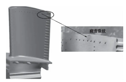
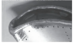
Figure 1 shows a typical turbine blade tip crack defect. Based on this, a method for remanufacturing and repairing the damaged blade tip of an aircraft engine turbine blade is proposed. A remanufacturing and repair solution is established, which includes removing the damaged part of the blade tip – molten welding and depositing solder (as shown in Figure 2) – acquiring blade point cloud – reconstructing the blade digital model – adaptive processing of the blade, to achieve adaptive repair of the blade geometric size accuracy and performance recovery. The quality and performance of the repaired blade meet the design requirements and can be used for real-time repair at the repair site, providing an effective solution for realizing batch repair processing of damaged components of aircraft engines.
Analysis of process difficulties
Due to the problem of casting accuracy, there are individual differences between the finished blade and the theoretical design model. The outline size of the blade is formed in the new state, and after a working cycle, it will produce different degrees of deformation and defects. Due to the individuality of the processed object, if it is repaired and processed according to the theoretical size of the design drawing, the shape accuracy of the original blade will be destroyed. If a set of processing codes needs to be regenerated according to the CAD model for each piece of processing, it will greatly affect the entire processing cycle of the part.
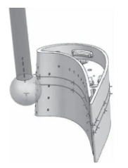
The blade tip has a complex structure, with a boss and cover plate 2 to 3 mm below the blade tip, and the narrowest width of the trailing edge tail seam is only 0.5 mm. The blade is an inner cavity structure, and there are many air film holes on the blade body surface. Chips easily enter the inner cavity and air film holes, making it difficult to clean.
Main technical requirements
- After the tip is repaired, the contours of the inner and outer curved surfaces conform to the design drawing and are smoothly connected to the original base blade shape.
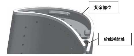
- The minimum wall thickness along the blade shape at the trailing edge of the tip is 0.41 mm, and the minimum wall thickness along the blade shape at other parts is 0.51 mm (as shown in Figure 3).
- The blade height dimension is guaranteed.
- The roughness is not greater than Ra0.8 μm.
- No chips or other impurities are allowed to remain in the inner cavity and air film holes.
- The repaired area is inspected by fluorescence to ensure that there are no cracks, inclusions, etc., and the inspection is carried out in accordance with the fluorescence inspection standards and acceptance standards.
2 Adaptive machining technology for blade tip damage repair
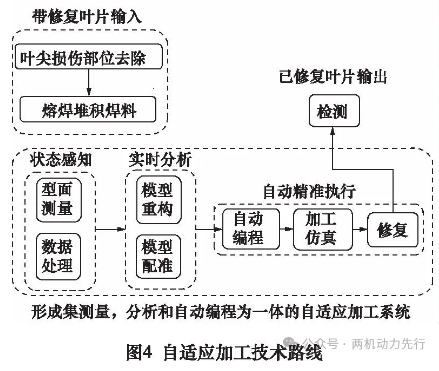
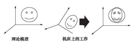
In view of the difficulties in the repair process of the blade tip of the turbine working blade, namely: the deformation of each repaired blade is inconsistent, the clamping position and angle are different, and the original precision casting accuracy is problematic. Such practical problems can be quickly detected online through adaptive processing technology for each part or part to be processed, and the actual shape and position distribution can be understood. Then, the system reconstructs the target digital model consistent with the design through the measured data, generates a unique personalized path trajectory to meet product manufacturing, and finally conforms to the design and the actual object. The adaptive processing technology route is shown in Figure 4.
Due to the personalized characteristics of the blank of the processed object, the reconstructed CAD model lacks a regular reference plane to find its coordinate system, and it is necessary to use registration technology to align its coordinate system. The two point sets in space are the theoretical model X{xi} and the measurement information P{pi} of the processed object. The P point set is rotated and translated to minimize the distance with the X point set, and the spatial transformation relationship between the measurement information P{pi} and the theoretical model information X{xi} is established. The spatial transformation relationship includes the rotation matrix R and the translation matrix T. Then, the nearest point pairing method is used to find a point in X that is closest to each point in P to pair it, forming a new point set X’, as shown in Figure 5.
3 Verification of adaptive machining technology for blade tip damage repair
The adaptive machining system includes adaptive machining software and hardware systems such as machine tools and cutting tools. The integration of the two is the key to ultimately achieving adaptive machining. In the repair work of a certain type of high-pressure turbine blade, the adaptive machining system was used to carry out the repair processing of the blades, and the repair processing and application verification of multiple engine blades were completed.
Test steps
- Step 1: After the damaged area of the blade tip to be repaired is filled by cladding and surfacing welding, the measurement information of the area near the damaged blade tip is obtained through in-machine detection.
- Step 2: Obtain the theoretical model information before blade tip repair.
- Step 3: Use the data registration to establish the spatial transformation relationship between the measurement information and the theoretical model information (the spatial transformation relationship includes rotation and translation), and obtain the rotation and translation correction, that is, the rotation and translation amount after the best fitting.
- Step 4: Generate the CLSF file of machining tool location track according to the theoretical model information, and generate the corrected tool location and tool axis vector in the CLSF file according to the correction amount in XYZ direction obtained in step 3.
- Step 5: Grinding and polishing the damaged area of the blade tip of the turbine blade using the modified tool track, so as to achieve complete restoration of the precision blade tip.
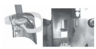
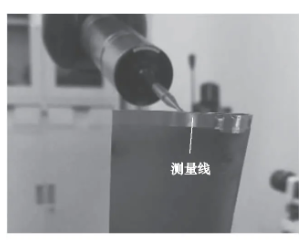
As shown in Figure 6, an RMP40 probe and aφ6 mm stylus ball are used for online detection. Twelve measurement points are obtained by optimizing the two sections near the blade tip. The generated measurement data files can be transmitted back to the computer software system, and the processing model can be automatically generated in UG based on the measurement data.
The test used a three-axis vertical machining center, and the blade was vertically cantilevered on the workbench through a quick-change tooling pallet, which facilitated repeated clamping accuracy during machining and feature processing in the subsequent process, as shown in Figure 7.
The generated machining tool trajectory CLSF file is shown in Figure 8.
Inner cavity and air film hole protection
During the test, the technical requirement that no chips or other impurities are allowed to remain in the inner cavity and air film holes was met. During the process test, the inner cavity and multiple air film holes of the blade were protected. This technical study uses functional glue to seal the inner cavity and air film holes, thereby protecting the holes. It is understood that when repairing such blades abroad, a liquid “multifunctional epoxy resin putty glue” is used to protect the cavity and air film holes. After cooling, it solidifies to achieve a protective effect. When heated to above 100°C, it melts and turns into “ash”, which can be blown off or removed by ultrasonic cleaning. There is no residue in the small holes. In subsequent batch engineering applications, the protection and cleaning of cavities and small holes will be particularly important, and it is necessary to continue to find more appropriate ways to prevent the entry of chips and impurities.
Test results
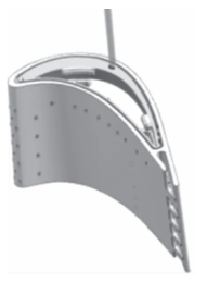
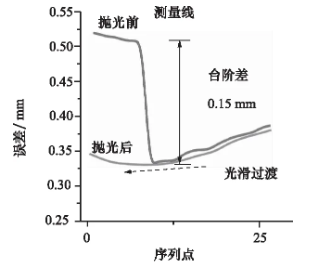
By measuring the tip profile of the repaired turbine blade, as shown in Figure 9, the shape meets the process technology requirements. From the appearance inspection, it can be seen that the blade repair area and the original profile are smoothly transitioned after adaptive polishing, as shown in Figure 10. The wall thickness of the inner and outer cavities is qualified, the surface roughness is below Ra0.8μm, and other technical indicators meet the process requirements. Through fluorescent inspection, the machining process did not cause new cracks and other defects.
Contact us
Thank you for your interest in our company! As a professional gas turbine parts manufacturing company, we will continue to be committed to technological innovation and service improvement, to provide more high-quality solutions for customers around the world.If you have any questions, suggestions or cooperation intentions, we are more than happy to help you. Please contact us in the following ways:
WhatsAPP:+86 135 4409 5201
E-mail:peter@turbineblade.net