In order to obtain the thermal insulation effect and temperature distribution law of thermal barrier coating on turbine blades, a certain type of gas turbine high-pressure turbine moving blade with internal cooling structure was used as the basic model. The cooling effect of high-pressure turbine moving blade with or without thermal barrier coating protection was numerically calculated by gas-heat coupling method, and the influence of thermal barrier coating on blade heat transfer was studied by changing the thickness of thermal barrier coating. The study found that after coating with thermal barrier coating, the temperature of the blade dropped significantly, the closer to the leading edge, the greater the temperature drop, and the temperature drop on the pressure side was greater than that on the suction side; the thermal barrier coating with a thickness of 0.05-0.2 mm can reduce the average temperature of the blade metal surface by 21-49℃; as the coating thickness increases, the temperature distribution inside the blade metal will become more uniform.
In the development of gas turbines, in order to improve the power and thermal efficiency of the engine, the turbine inlet temperature is also increasing. The turbine blades are subjected to the impact of high-temperature gas. When the turbine inlet temperature continues to increase, air cooling alone can no longer meet the requirements. Thermal barrier coatings, as an effective means to improve the high temperature resistance and corrosion resistance of materials, have been increasingly used.
Thermal barrier coatings are generally adhered to the blade surface by plasma flame spraying or electron beam deposition. They have the characteristics of high melting point and resistance to thermal shock, which can improve the ability of turbine blades to resist oxidation and thermal corrosion, reduce blade temperature, and extend the service life of blades. Alizadeh et al. studied the thermal insulation effect of 0.2 mm thermal barrier coatings by gas-heat coupling numerical simulation. The results showed that the maximum temperature of the blade was reduced by 19 K and the average temperature was reduced by 34 K. Prapamonthon et al. studied the effect of turbulence intensity on the cooling efficiency of thermal barrier coating blades. The results showed that thermal barrier coatings can increase the comprehensive cooling efficiency of the blade surface by 16% to 20% and 8% at the trailing edge of the blade. Zhu Jian et al. established a one-dimensional steady-state model for coated blades from a thermodynamic perspective, and theoretically analyzed and calculated the thermal insulation effect of thermal barrier coatings. Shi Li et al. conducted a numerical study on C3X with thermal barrier coatings. A 0.3 mm ceramic layer can reduce the blade surface temperature by 72.6 K and increase the comprehensive cooling efficiency by 6.5%. The thermal barrier coating has no effect on the distribution of the cooling efficiency of the blade surface. Zhou Hongru et al. conducted a numerical study on the leading edge of turbine blades with thermal barrier coatings. The results showed that thermal barrier coatings can not only reduce the operating temperature of metal blades and the temperature gradient within the blades, but also resist the thermal shock of inlet hot spots to a certain extent. Yang Xiaoguang et al. calculated the two-dimensional temperature field distribution and stress of guide vanes with thermal barrier coatings by giving the heat transfer coefficients of the inner and outer surfaces of the blades. Wang Liping et al. conducted a three-dimensional gas-thermal coupling analysis on turbine guide vanes with composite cooling structures and studied the effects of coating thickness and gas radiation on the coating temperature field. Liu Jianhua et al. analyzed the thermal insulation effect of thermal barrier coatings for Mark II cooling blades with multi-layer thermal barrier coatings by internally setting the heat transfer coefficient and external gas-thermal coupling.
Calculation method
Computational Model
The thermal barrier coating is located between the high-temperature gas and the surface of the blade alloy substrate, and is composed of a metal bonding layer and a thermal insulation ceramic layer. Its basic structure is shown in Figure 1. When constructing the calculation model, the bonding layer with higher thermal conductivity in the thermal barrier coating structure is ignored, and only the thermal insulation ceramic layer with lower thermal conductivity is retained.
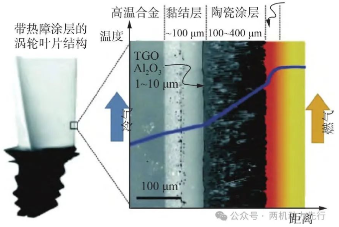
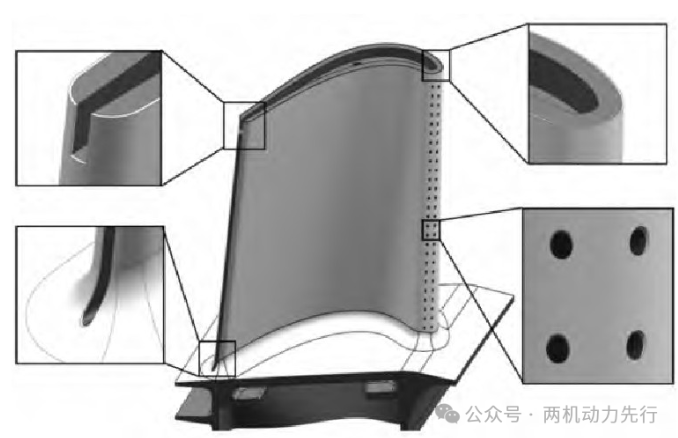
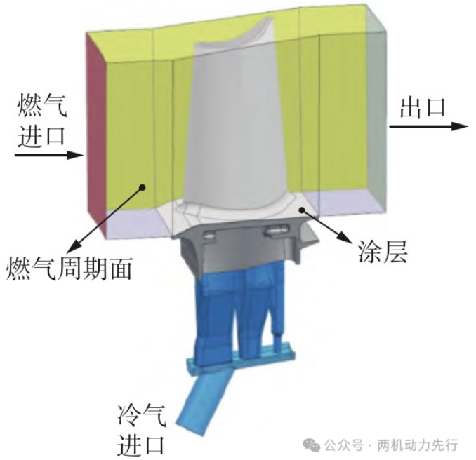
Figure 2 shows the blade model after being coated with thermal barrier coating. The blade contains a multi-channel rotary cooling structure, with two exhaust film cooling holes on the leading edge, a middle slit structure on the trailing edge, and an H-shaped groove structure on the blade top. The thermal barrier coating is only sprayed on the blade body and the lower edge plate surface. Since the temperature below the blade root is low and is not the focus of research, in order to reduce the number of computational grids, the part below the root is ignored when setting the computational model, and the computational domain model shown in Figure 3 is constructed.
Numerical calculation method
The internal geometry of the turbine cooling blade is relatively complex, and it is difficult to use structured grids. The use of unstructured grids significantly increases the amount of calculation. In this regard, this paper uses a polyhedral grid generator to mesh the blade and gas domain. Mesh division,The mesh model is shown in Figure 4.
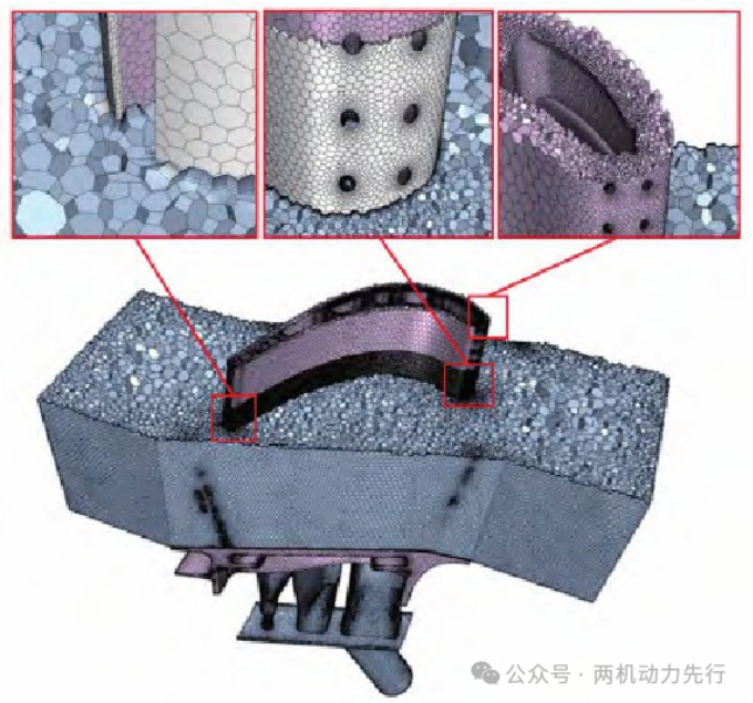
In the calculation model, the thickness of the thermal barrier coating is extremely small, less than 1/10 of the thickness of the blade wall. For this reason, this paper uses a thin mesh generator to divide the thermal barrier coating into three layers of polygonal prismatic meshes. The number of thin mesh layers has been verified to be independent, and the number of thin mesh layers has almost no effect on the blade temperature field.
The fluid domain adopts the Realizable K-Epsilon Two-Layer model in the Reynoldsaveraged Navier-Stokes equations (RANS) turbulence model. This model provides greater flexibility for the mesh processing of the entire y+ wall. It can not only handle fine meshes (i.e., low Reynolds number type or low y+ meshes) well, but also handle intermediate meshes (i.e., 1<y+<30) in the most accurate way, which can effectively balance stability, computational cost and accuracy.
Boundary conditions
The gas inlet is set as a total pressure stagnation inlet, the cooling air inlet is a mass flow inlet, and the outlet is set as a static pressure outlet. The coating surface in the gas channel is set as a fluid-solid coupling surface, the coating and the blade metal surface are set as a solid interface, and the two sides of the channel are set as a rotation period. Both the cold gas and the gas are ideal gases, and the gas heat capacity and thermal conductivity are set using the Sutherland formula. The corresponding calculation boundary conditions are: the total pressure of the mainstream inlet of the gas channel is 2.5 MPa, the inlet temperature distribution with radial temperature gradient is shown in Figure 5, the cold gas inlet flow rate of the cold channel in the blade is 45 g/s, the total temperature is 540℃, and the outlet pressure is 0.9 MPa. The blade material is a nickel-based single crystal high-temperature alloy, and the thermal conductivity of the material changes with temperature. As far as existing materials are concerned, thermal barrier coatings generally use stable yttria zirconium oxide (YSZ) materials or zirconium oxide (ZrO2), whose thermal conductivity changes little with temperature, so the thermal conductivity is set to 1.03 W/(m·K) in the calculation.
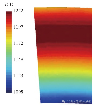
Figure 5 Gas inlet temperature distribution
Blade surface temperature
Figures 6 and 7 show the surface temperature distribution of the uncoated blade and the metal surface temperature distribution of the blade at different coating thicknesses, respectively. It can be seen that as the coating thickness continues to increase, the metal surface temperature of the blade gradually decreases, and the temperature distribution law of the metal surface of the blade at different thicknesses is basically the same, the temperature in the middle of the pressure surface is lower, and the temperature at the blade tip is higher. The blade tip is usually the most difficult part of the entire blade to cool, and the groove ribs at the blade tip are difficult to be directly cooled by cold air. In the calculation model, the coating only covers the surface of the blade body, and the blade tip is not covered with coating. There is no barrier effect on the heat from the gas side of the blade tip, so the high temperature area at the blade tip always exists.
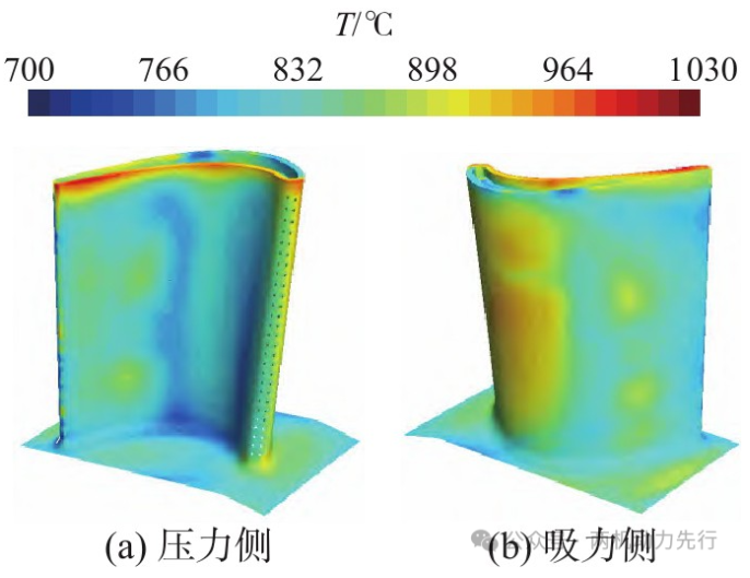
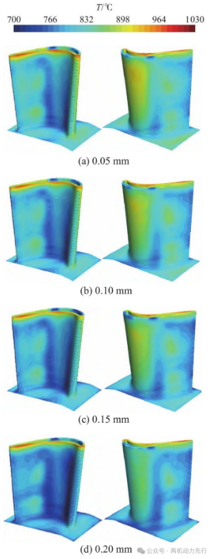
Figure 8 shows the curve of the average temperature of the blade metal surface changing with thickness. It can be seen that the average temperature of the blade metal surface decreases with the increase of coating thickness. This is because the thermal conductivity of the thermal barrier coating is low, which increases the thermal resistance between the high-temperature gas and the metal blade, effectively reducing the temperature of the blade metal surface. When the coating thickness is 0.05 mm, the average temperature of the blade body decreases by 21°C, and then as the thickness of the thermal barrier coating increases, the temperature of the blade surface continues to decrease; when the coating thickness is 0.20 mm, the average temperature of the blade body decreases by 49°C. This is basically consistent with the thermal insulation effect measured by Zhang Zhiqiang et al. through the cold effect test.
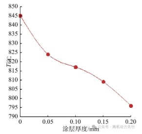
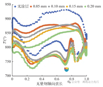
Figure 9 is a curve showing the change of the surface temperature of the blade section along the axial chord length. As can be seen from Figure 9, under different thicknesses of thermal barrier coatings, the temperature change trend along the axial chord length is basically the same, and the temperature of the suction surface is significantly higher than the temperature of the pressure surface. In the direction of the axial chord length, the temperature of the pressure surface and the suction surface first decreases and then increases, and there is a certain fluctuation in the trailing edge area, which is caused by the structural form of the split-slit spray cooling in the middle of the trailing edge. At the same time, the temperature of the blade coated with the thermal barrier coating drops significantly, and the temperature drop on the suction surface is significantly greater than that on the pressure surface. The temperature drop gradually decreases from the leading edge to the trailing edge, and the closer to the leading edge of the blade, the greater the temperature drop.
The uniformity of the blade metal temperature affects the thermal stress level of the blade, so this paper uses the temperature uniformity index to measure the temperature uniformity of the solid blade. Temperature uniformity index:
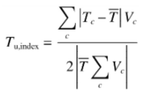
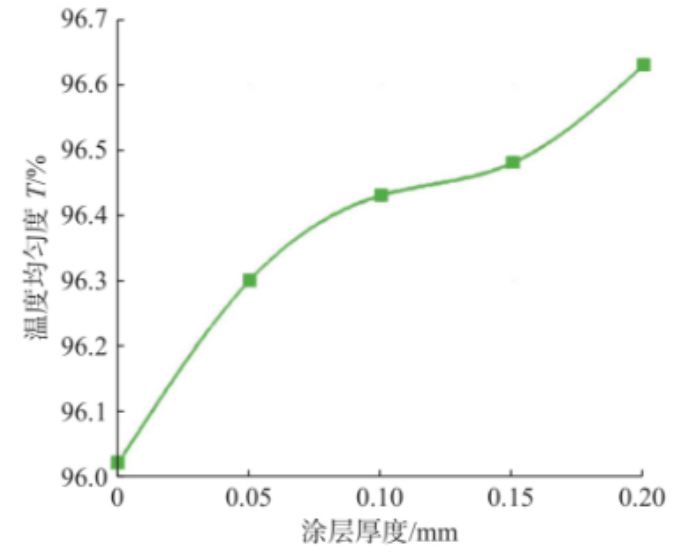
Where: c is the volume of each unit, T- is the volume average of temperature T, Tc is the temperature value in the grid unit, and Vc is the volume of the grid unit. If the volume temperature field is uniformly distributed, the volume uniformity index is 1. As can be seen from Figure 10, after spraying the thermal barrier coating, the temperature uniformity of the blade is significantly improved. When the coating thickness is 0.2 mm, the temperature uniformity index of the blade is increased by 0.4%.
Coating surface temperature
The temperature change of the coating surface is shown in Figure 11. As can be seen from Figure 11, as the coating thickness increases, the surface temperature of the thermal barrier coating continues to increase, which is exactly the opposite of the average temperature change trend of the blade surface. As the thermal resistance increases in the coating thickness direction, the temperature difference between the coating surface and the blade surface gradually increases, and the accumulated heat on the surface is more difficult to diffuse to the metal blade. When the coating thickness is 0.20 mm, the temperature difference between the inside and outside of the coating reaches 86°C.
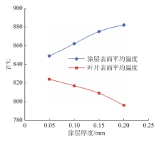
Figure 11 Average temperature changes of coating surface and blade surface
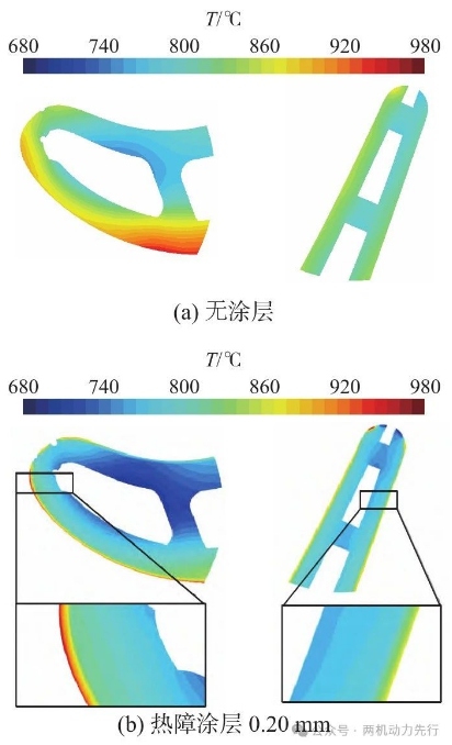
Figure 12 shows the temperature distribution of the leading and trailing edges of blades with and without thermal barrier coatings. After the surface is coated with thermal barrier coatings, the cross-sectional temperature of the blade is significantly reduced, and the temperature gradient is alleviated. This is because after the thermal barrier coating is applied, the heat flux density in the coating is reduced. At the same time, since the thermal barrier coating material has a low thermal conductivity, the temperature changes inside the thermal barrier coating solid are very drastic.
Contact us
Thank you for your interest in our company! As a professional gas turbine parts manufacturing company, we will continue to be committed to technological innovation and service improvement, to provide more high-quality solutions for customers around the world.If you have any questions, suggestions or cooperation intentions, we are more than happy to help you. Please contact us in the following ways:
WhatsAPP:+86 135 4409 5201
E-mail:peter@turbineblade.net