1 Development of aviation gas turbine engines
As the performance requirements for aircraft for transportation, military, production and other purposes increased, the earliest piston engines could no longer meet the needs of high-speed flight. Therefore, since the 1950s, gas turbine engines have gradually become mainstream.
In 1928, Sir Frank Whittle of the United Kingdom pointed out in his graduation thesis “Future Development in Aircraft Design” while studying at the military academy that under the technical knowledge at that time, the future development of propeller engines could not adapt to the needs of high altitude or flight speeds exceeding 800km/h. He first proposed the concept of what is now called a jet engine (motor engine): compressed air is provided to the combustion chamber (combustion) through a traditional piston, and the high-temperature gas generated is directly used to propel flight, which can be regarded as a propeller engine plus a combustion chamber design. In subsequent research, he abandoned the idea of using a heavy and inefficient piston and proposed using a turbine (turbine) to provide compressed air to the combustion chamber, and the power of the turbine was obtained from the high-temperature exhaust gas. In 1930, Whittle applied for a patent, and in 1937, he developed the world’s first centrifugal turbojet engine, which was officially used in the Gloster E.28/39 aircraft in 1941. Since then, gas turbine engines have dominated aviation power and are an important symbol of a country’s scientific and technological industrial level and comprehensive national strength.
Aircraft engines can be divided into four basic types according to their uses and structural characteristics: turbojet engines, turbofan engines, turboshaft engines, and turboprop engines:
Aviation gas turbine engines are referred to as turbojet engines, which are the earliest gas turbine engines used. From the perspective of the way thrust is generated, turbojet engines are the simplest and most direct engines. The reasoning relies on the reaction force generated by the high-speed injection of the vortex. However, the high-speed airflow takes away a lot of heat and kinetic energy at the same time, causing great energy loss.
The turbofan engine divides the air flowing into the engine into two paths: the inner duct and the outer duct, which increases the total air flow and reduces the exhaust temperature and speed of the inner duct airflow.
Turboshaft and turboprop engines do not generate thrust by airflow injection, so the exhaust temperature and speed are greatly reduced, the thermal efficiency is relatively high, and the engine fuel consumption rate is low, which is suitable for long-range aircraft. The speed of the propeller generally does not change, and different thrusts are obtained by adjusting the blade angle.
The propfan engine is an engine between turboprop and turbofan engines. It can be divided into propfan engines with ducted propeller cases and propfan engines without ducted propeller cases. The propfan engine is the most competitive new energy-saving engine suitable for subsonic flight.
Civil aerospace engines have gone through more than half a century of development. The structure of the engine has evolved from the early centrifugal turbine engine to the single-rotor axial flow engine, from the twin-rotor turbojet engine to the low bypass ratio turbofan engine, and then to the high bypass ratio turbofan engine. The structure has been continuously optimized with the pursuit of efficiency and reliability. The turbine inlet temperature was only 1200-1300K in the first generation of turbojet engines in the 1940s and 1950s. It increased by about 200K with each aircraft upgrade. By the 1980s, the turbine inlet temperature of the fourth generation advanced fighter jets reached 1800-2000K[1].
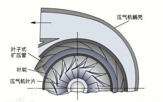
The principle of centrifugal air compressor is that the impeller drives the gas to rotate at high speed, so that the gas generates centrifugal force. Due to the expansion pressure flow of the gas in the impeller, the flow rate and pressure of the gas after passing through the impeller are increased, and compressed air is continuously produced. It has a short axial dimension and a high single-stage pressure ratio. Axialflow air compressor is a compressor in which the air flow basically flows parallel to the axis of the rotating impeller. The axial flow compressor consists of multiple stages, each stage contains a row of rotor blades and a subsequent row of stator blades. The rotor is the working blades and the wheel, and the stator is the guide. The air is first accelerated by the rotor blades, decelerated and compressed in the stator blade channel, and repeated in the multi-stage blades until the total pressure ratio reaches the required level. The axial flow compressor has a small diameter, which is convenient for multi-stage tandem use to obtain a higher pressure ratio.
Turbofan engines usually use bypass ratio, engine pressure ratio, turbine inlet temperature, and fan pressure ratio as design parameters:
- Bypass ratio (BPR): The ratio of the mass of gas flowing through the outlet ducts to the mass of gas flowing through the inner ducts in the engine. The rotor at the front of a turbojet engine is usually called the low-pressure compressor, and the rotor at the front of a turbofan engine is usually called the fan. The pressurized gas passing through the low-pressure compressor passes through all parts of the turbojet engine; the gas passing through the fan is divided into the inner and outer ducts. Since the emergence of turbofan engines, BPR has been increasing, and this trend is particularly evident in civil turbofan engines.
- Engine pressure ratio (EPR): The ratio of the total pressure at the nozzle outlet to the total pressure at the compressor inlet.
- Turbine inlet emperature: The temperature of the combustion chamber exhaust when it enters the turbine.
- Fan compression ratio: Also referred to as compression ratio, the ratio of the gas pressure at the compressor outlet to the gas pressure at the inlet.
Two efficiencies:
Thermal efficiency: A measure of how efficiently an engine converts the heat energy generated by combustion into mechanical energy.
Propulsion efficiency: A measure of the proportion of the mechanical energy generated by the engine that is used to propel the aircraft.